Experiment 8 - ATmega328 Working with Registers/Arithmetic Operations/Logical Operations
As has been pointed out before, most microprocessors do the same basic operations. Knowing and understanding what these "basic operations" are, makes adapting to a new microprocessor easy. In many cases it is simply a matter of identifying different instruction mnemonics. In experiments 1 to 7 we explored Intel 8080's "basic operations". In this and subsequent experiments, we will use this knowledge as a base to explore the capabilities of a more modern processor, the Atmel ATmega328. Our approach in Experiments 8 to 10 will be to work our way through Intel 8080 experiments comparing and at times contrasting the instruction sets of the two processors. In Experiment 11, we take a look at the ATmega328's built-in peripherals and explore how to write assembly code to use them. In Experiment 12, we will play around with AVR Tiny BASIC and learn how to customize it for special applications.
The ATmega328 is one of a large family of microprocessors that are affordable and adaptable to a wide variety of applications including the popular Arduino computer boards. Let's be clear. we are not suggesting that high level languages be abandoned in favor of assembly. Rather, we do the study for its educational value striving for a better understanding of the internal operation of the microprocessor. Of course, it may be that, in certain applications, assembly language or a combination of high-level language and assembly will provide a better solution.
Preparing the SparkFun Redboard
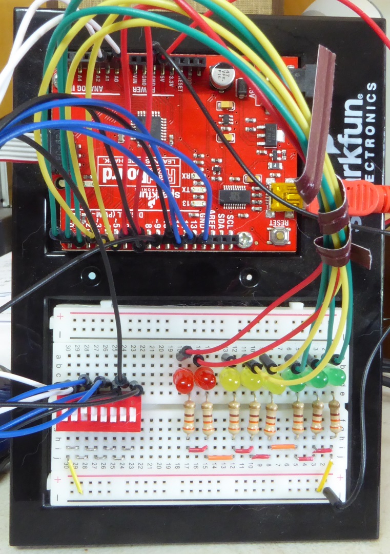
The SparkFun Inventor's Kit (SIK KIT-13969) contains many of the parts we will use in the following experiments. Alternatively, the Redboard can be ordered alone (DEV-13975) and the remaining parts (breadboard, LEDs, jumper wires, etc.) obtained separately. The kit includes some but all the parts we need. The breadboard, LEDs, and jumper wires in the kit are fine. The kit's 330 ohm resistor leads are too small in diameter to make good connection in the breadboard. 330 ohm 1/4 watt resistors purchased separately work much better. Pictured below is the SparkFun Redboard.
In order to match the ATmega32 experience as closely to the Intel 8080 experiments, we need Data LEDs and sense switches. Pictured below is our version of sense switches and Data LEDs built on the SIK breadboard. The short jumper wires are made from No. 22 hook-up wire. The eight position DIP switch can be order from Mouser (Part no. 706-78B08ST).
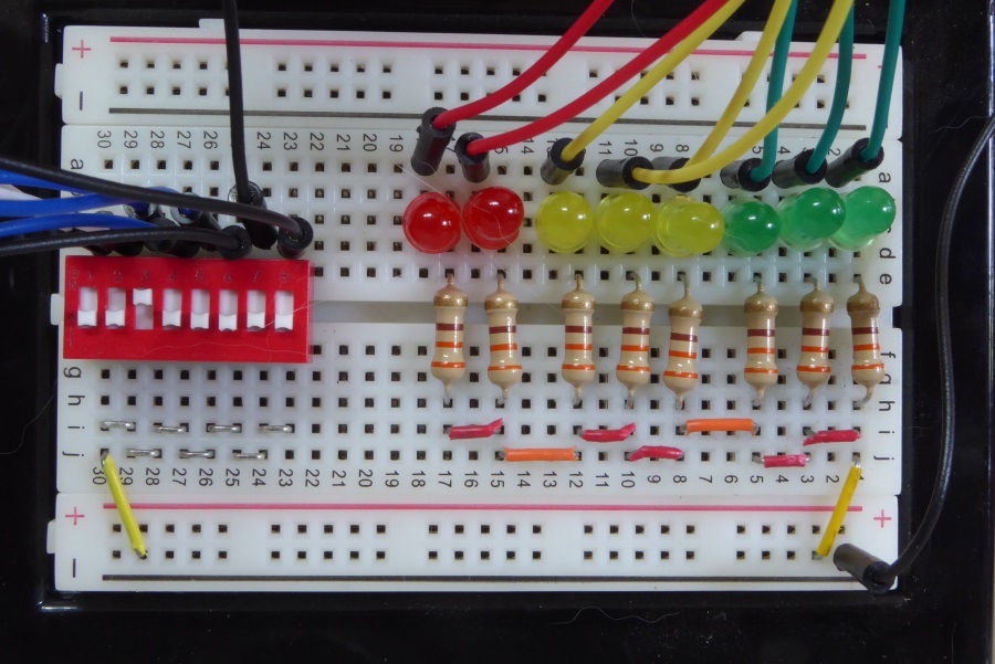
The eight LEDs positive leads (rounded side) are patched from left to right to pins 7 to 0 of the Redboard (PORTD bits 7 to 0). The LED leads are trimmed so that the LED fits snugly against the breadboard. The chosen LED colors and spacing complement the octal orientation of the initial Intel 8080 experiments. The negative (flat side) of each LED is connected to common ground through 330 ohm resistors.
The numericly labeled side of the DIP switch (top in image above) is patched as follows: (1) the left most two switches (labeled 1 and 2) are patched to pins ADC1 and ADC0 (PORTC bits 1 and 0) respectively of the Redboard, and (2) right most six switches (labeled 3 to 8) are patched to pins 13 to 8 (PORTB bits 5 to 0) respectively of the Redboard. All pins of the unnumbered side of the DIP switch are connected to common ground.
The DIP switches are open when positioned away from the numbers (down in image above). This is important because the AVR programmer does not work if one or all of pins 11, 12, or 13 are shorted to ground.
Note: Keep the switches positioned down (open) during flash programming.
The Data LEDs light when the bits on PORTD are cleared, the opposite of the way they worked on the Altair simulation. In addition, not all bits of the ATmega328's PORTB are available for use. Bits 6 and 7 are used for the 16 MHz crystal connection. This complicates using the sense switches, as they are split between PORTB and PORTC. To overcome these complications, we use two subroutines to access Data LEDs and sense switches.
To display a byte in the Data LEDs, move it to register r16 and use the code "call LEDout". Similarly, to input from the sense switches, use the code "call ssinp". The inputted byte is returned in register r16.
After wiring the LEDs and sense switches, work through Experiment 0 below to test.
Experiment 8-0 - Setting Up the AVR Programmer and Testing the LEDs and Sense Switches
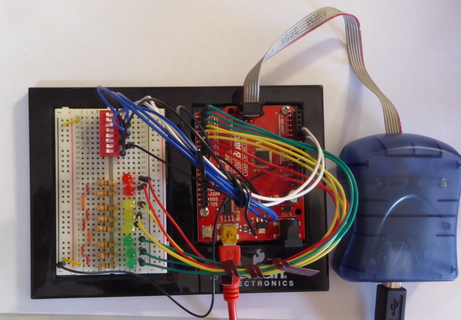
The AVR ISP MK2 can be ordered from Mouser (Part no. 909-AVR-ISP-MK2). The programmer pictured below is an older version, but operational is the same. The AVR ISP MK2 plugs into the ISP header on the Redboard as shown. It is powered by the USB cable that also provides communication with ATMEL's Studio 7 downloadable here.
Power up the SparkFun Redboard and then power up the attached AVR ISP MK2. Follow these steps:
We are ready to begin examples in Experiment 8.
Memory Map for the AT mega328
The Intel 8080 program/data memory map was very simple: 0x0000 to 0xFFFF of external memory. Program and data overlapped in this memory space. The I/O map was separate covering 0x00 to 0xFF and like program/data memory, external.
With huge advances to component density, processors like the ATmega328 are able to incorporate program/data memory and peripherals internally. Separate program and data memory maps are shown below.
|
|
We describe the working registers in the next section. The 64 I/O registers plus the 160 extended I/O registers provide for access to and control of ATmega328's internal peripherals. SRAM (2048 bytes) is available for general data storage. Other versions of the ATmega have varying amounts of program and data memory.
I/O registers have a wide range of function. Some I/O registers provide for data transfer to and from the ATmega328. Other are used to set options or read the the status of peripherals. In this case, the individual bits, groups of bits, or entire bytes are used. As we encounter peripherals, we will see how I/O registers are used.
Note: Program memory is non-volatile; it is retained after power down. Data memory is volatile and lost when power is removed.
Experiment 8-1 - Working with AT mega328 Registers
Loading a Register with a Constant Value
| Basic Operation Example | Intel 8080 | ATmega328 |
| Load a register with a constant | MVI B, 0x3F Register B loaded with 0x3F |
LDI R20, 0x3F Register R20 loaded with 0x3F |
Moving a Value from Register to Register
| Basic Operation Example | Intel 8080 | ATmega328 |
| Moving a value from register to register | MOV B,H B register value acquires value of H register |
MOV R2, R17 Register R2 value acquires value of register R17 |
Try it!
Note: The examples below are taken from Intel 8080 Experiment 1 and are, in most cases, simple translations to ATmega328 code that require little comment. Where there are additional considerations, notes are provided. I needed, use the link to refer back to the Intel 8080 experiment and example. For each example, change the Target Jump located near the beginning of "main.asm" to the label of the code being tested.
Reminder: With the SparkFun Redboard, inputting from the Sense Switches and outputting to the Data LEDs is handled with utility subroutines "ssinp" and "LEDout" respectively. In both cases, R16 is the input/output parameter passed between the subroutine and the calling program. Refer to Experiment 9 Example 1 for details.
Experiment 8-1 Example 1. Move the value 10 to the a register and display the result in the Data LEDs.
;
; Experiment 1 Example 1 - Load a register with an 8-bit value and display
in Data LEDS
;
exmp1_1:
ldi r16, 0b00001010 ;012Q
-> r16
call LEDout
;r16 -> LEDS
rjmp exmp1_1 ;loop
Open the ATMEL STUDIO project Experiment_8. Change the Target Jump line in the assembly program "main.asm" to "exmp1_1". Build the solution and program the ATmega328 flash memory to test the program. The LEDs should display 00 001 010.
Note the following:
The LDI instruction only works with registers R16 TO R31.
The LEDout subroutine outputs R16 to the Data LEDs. The decision to use R16 in "call LEDout" was arbitrary; any register would work with the OUT instruction.
Most modern processors do not have a HALT instruction, so we terminate the program with an endless loop.
The ATmega328 assembler is not case sensitive. "r16" works the same as "R16".
Experiment 8-1 Example 2. Load register R17 with 125Q and then move it to R16 for display in the Data LEDs.
;
; Experiment 1 Example 2 - Load a register (r17) with 125Q, move it another
register (r16), and display in Data LEDS
;
exmp1_2:
ldi r17,
0b01010101 ;125Q -> r17
mov r16, r17
;r17 -> r16
call LEDout
;r16 -> LEDS
rjmp exmp1_2
Change the Target Jump line to "exmp1_2". Build the solution and program the ATmega328 flash memory to test the program. The Data LEDs should display 01 010 101.
Experiment 8-2 - Arithmetic Operations with the ATmega328
The ATmega328's arithmetic operators parallel very closely with the Intel 8080. The table below provides a summary comparison. The outstanding difference is that, unlike the Intel 8080, arithmetic operation can be performed with any ATmega328 register. For this reason, the ATmega328 operational instructions must include as the first parameter, the destination register for the result.
| Arithmetic Operation | Intel 8080 | ATmega328 | Flags Affected |
| Register Add | ADD r | ADD Rd, Rr | Z,C,N,V,H |
| Register Add with Carry | ADC r | ADC Rd, Rr | Z,C,N,V,H |
| Add Immediate | ADI K | N.A. | |
| Add Immediate with Carry | ACI K | N.A. | |
| Register Subtract | SUB r | SUB Rd, Rr | Z,C,N,V,H |
| Register Subtract with Carry (Borrow) | SBB r | SBC Rd, Rr | Z,C,N,V,H |
| Subtract Immediate | SBI K | SUBI Rd, K | Z,C,N,V,H |
| Subtract Immediate with Carry (Borrow) | SBI r | SBCI Rd, K | Z,C,N,V,H |
The table below compares the status word of the Intel 8080 to the status register of the ATmega328.
|
Intel 8080 Processor Status Word (PSW) |
ATmega328 Status Register (SREG) |
ATmega328 Bit No. |
Comment |
| Carry (C) | Carry (C Flag) | 0 | C - The Carry Flag indicates a carry in an arithmetic or logic operation. |
| Zero (Z) | Zero (Z Flag) | 1 | Z - The Zero Flag indicates a zero result in an arithmetic or logic operation. |
| Sign (S) | Negative (N Flag) | 2 | N - The Negative Flag indicates a negative result in an arithmetic or logic operation; i.e. bit 7 = 1). |
| N.A. | Two's Complement Overflow (V Flag) | 3 | V - The Two’s Complement Overflow Flag supports two’s complement arithmetic. |
| N.A. | Sign (S Flag) | 4 | S - The Sign Flag is exclusive-or between Negative Flag N and Two’s Complement Overflow Flag V. |
| Auxiliary Carry (AC) | Half Carry (H Flag) | 5 | H - The Half Carry Flag indicates a carry out of bit 3 in some arithmetic operations. |
| N.A. | Copy Storage (T Flag) | 6 | T - The Temporary Flag provides 1-bit storage using BLD (Bit LoaD) and BST (Bit STore). |
| N.A. | Global Interrupt Enable (I Flag) | 7 | I - The Global Interrupt Enable Flag must be set for the interrupts to be enabled. |
The ATmega328 has additional arithmetic operations summarized in the table below.
| Arithmetic Operation | ATmega328 | Comment | Flags Affected |
| Register Twos Complement | NEG Rd | With the Intel 8080, we would use two instructions to accomplish this. E.g., CMA followed by INR A | Z,C |
| Register Multiply Unsigned (0 to 255) | MUL Rd, Rr | Result in R1 (high byte) and R0 (low byte). d, r = 0, 1 ...30, 31 | Z,C |
| Register Multiply Signed (-128 to 127) | MULS Rd, Rr | Result in R1 (high byte) and R0 (low byte). d, r = 16, 17 ... 30, 31 | Z,C |
| Register Multiply Signed with Unsigned | MULSU Rd, Rr | Result in R1 (high byte) and R0 (low byte). d, r = 16, 17 ... 22, 23 | Z,C |
| Register Fractional Multiply | See the AVR Instruction Set Manual for details. |
Try it!
The examples below are taken from Intel 8080 Experiment 2 and are, in most cases, simple translations to ATmega328 code requiring little comment. Where there are differences, notes are provided. The link at the beginning of each example points back to the Intel 8080 example for reference.
To test an example, change the "Target Jump" located near the beginning of the program to the start label of that example.
Experiment 8-2 Example 1. Create and test code that adds an immediate data value.
We overcome the absence of an add immediate instruction by subtracting the negative of 12 (highlighted in green).
;
; Experiment 2 Example 1a - Add 25 and 12 then display. The answer is 37 or 045Q.
;
; Using subtract immediate
;
exmp2_1a:
ldi
r16, 25 ;25 -> r16
subi
r16, -12 ;r16 - (-12) -> r16
call
LEDout ;r16 -> LEDs
rjmp exmp2_1a
Change the Target Jump line to "exmp2_1a". Build the solution and program the ATmega328 flash memory to test the program. The Data LEDs should display 00 100 101.
Next redo the example replacing the subtract immediate instruction with an "add immediate" macro (highlighted in yellow).
. . .
;
; Add Immediate Macro
;
.macro addi
subi @0, -@1
;subtract the negative of an immediate value
.endmacro
;
. . .
;
; Experiment 2 Example 1b - Add 25 and 12 then display. The answer is 37 or 045Q.
;
; Using add immediate macro
;
exmp2_1b:
ldi
r16, 25
;25 -> r16
addi
r16, 12
;r16 + 12 -> r16
call
LEDout
;r16 -> LEDs
rjmp exmp2_1b
Change the Target Jump line to "exmp2_1b". Build the solution and program the ATmega328 flash memory to test the program. The Data LEDs should display 00 100 101.
Note: Macro definitions like the "addi" should appear at the beginning of the assembly program before the macro is used.
Experiment 8-2 Example 2. Add 25 and 12 with so that the Carry Bit will be added into the sum.
We cannot use SUBI with the carry set, because this would subtract rather than add the carry from the sum. Instead, we load a second working register (say R17) immediately with 12 and then use ADC (add registers with carry).
;
; Experiment 2 Example 2 - Add 25 and 12 with Carry then display. The answer is
38 or 046Q.
;
; Using subtract immediate
;
exmp2_2:
sec
;Set Carry
ldi
r16, 25 ;25 -> r16
ldi
r17, 12 ;12 -> r17
adc
r16, r17 ;r16 + r17 -> r16
call LEDout ;r16 -> LEDs
rjmp exmp2_2
Change the Target Jump line to "exmp2_2". Build the solution and program the ATmega328 flash memory to test the program. The Data LEDs should display 00 100 110.
Experiment 8-2 Example 3. Create and test code that subtracts an immediate value.
;
; Experiment 2 Example 3 - Subtract 12 from 25 then display. The answer is 13 or
015Q.
;
; Using subtract immediate
;
exmp2_3:
ldi
r16,25
;25 -> r16
subi r16,12
;r16 - 12 -> r16
call LEDout
;r16 -> LEDs
rjmp exmp2_3
Change the Target Jump line to "exmp2_3". Build the solution and program the ATmega328 flash memory to test the program. The Data LEDs should display 00 001 101.
Experiment 8-2 Example 4. Subtract 12 from 25 with SBCI so that the Borrow (Carry) Bit will be subtracted along with the immediate value.
;
; Experiment 2 Example 4 - subtract 12 from 25 with borrow then display. The
answer is 12 or 014Q.
;
; Using subtract immediate
;
exmp2_4:
sec
;Set Carry
ldi r16,25
;25 -> r16
sbci r16,12
;12 -> r17
call LEDout
;r16 -> LEDs
rjmp exmp2_4
Change the Target Jump line to "exmp2_4". Build the solution and program the ATmega328 flash memory to test the program. The Data LEDs should display 00 001 100.
Experiment 8-2 Example 5 - Create and test code that verifies that the negative of a negative is a positive.
;
; Experiment 2 Example 5 - Show that -(-25) = 25.
;
; Using the ATmega328 negation instruction (NEG)
;
exmp2_5:
ldi
r16,-25
;-25 -> r16
neg
r16
;-(-25) -> r16
call
LEDout
;r16 -> LEDs
rjmp
exmp2_5
Change the Target Jump line to "exmp2_5". Build the solution and program the ATmega328 flash memory to test the program. The Data LEDs should display 00 011 001.
Note: NEG is equivalent of the Intel 8080 instructions CMA followed by INR A (twos complement of A).
Experiment 8-2 Example 6 - Create and test code that verifies the variety of addition and subtraction examples shown in the table below.
Use the code of Example 2 above (adding and subtracting with two registers) substituting the appropriate instruction (ADD or SUB) and the table values to verify the results indicated.
| A | Operation | B | = | = (in Binary) | = (in Octal) |
| 25 | + | 18 | 43 | 00 101 011 | 053 |
| 25 | + | (-18) | 7 | 00 000 111 | 007 |
| -25 | + | 18 | -7 | 11 111 001 | 371 |
| -25 | + | -18 | -43 | 11 010 101 | 325 |
| 25 | - | 18 | 7 | 00 000 111 | 007 |
| -25 | - | 18 | -43 | 11 010 101 | 325 |
| -25 | - | -18 | -7 | 11 111 001 | 371 |
;
; Experiment 2 Example 6a - Add two values then display. The answer is 43 or
053Q for first value in table.
;
; Using two registers
;
exmp2_6a:
ldi
r16,25
;25 -> r16
ldi
r17,18
;18 -> r17
add r16,r17
;r16 + r17 -> r16
call LEDout
;r16 -> LEDs
rjmp exmp2_6a
;
; Experiment 2 Example 6b - Subtract two values then display. The answer is 7 or
007Q for first values in table.
;
; Using two registers
;
exmp2_6b:
ldi r16,25
;25 -> r16
ldi r17,18
;18 -> r17
sub r16,r17
;r16 - r17 -> r16
call LEDout
;r16 -> LEDs
rjmp exmp2_6b
Change the Target Jump line to "exmp2_6a". Build the solution and program the ATmega328 flash memory to test the program for the listed values. Repeat for "exmp2_6b".
Experiment 8-3 - Logical Operations with the ATmega328
As with the ATmega328's arithmetic operators, the logical operators are very similar to the Intel 8080. The table below provides a summary comparison.
| Arithmetic Operation | 8080 | ATmega328 |
| Register And | AND r | AND Rd, Rr |
| And Immediate | ANI K | ANDI Rd, K |
| Register Or | ORA r | OR Rd, Rr |
| Or immediate | ORI K | ORI Rd, K |
| Register Exclusive-Or | XRA r | EOR Rd, Rr |
| Exclusive-Or Immediate | XRI K | N.A.* |
* The ATmega328 is missing the exclusive-or immediate instruction. A simple substitution is to load the constant into a second working register and use the EOR instruction to exclusive-or it with the destination register.
Try it!
Experiment 8-3 Example 1 - Create and test code that performs each logic operation (or, and, and exclusive-or). Assume one operand is 10101010B and the other is 00001111B.
;
; Experiment 3 Example 1a - Basic logical operations: OR. The result is
0b10101111.
;
; Using OR immediate to set bits
;
; Turns on lower four bits and leaves upper four bits unchanged; i.e., sets the
lower four bits.
;
exmp3_1a:
ldi
r16,0b10101010
;0b010101010 -> r16
ori r16,0b00001111
;r16 OR 0b00001111 -> r16
call LEDout
;r16 -> LEDs
rjmp exmp3_1a
;
; Experiment 3 Example 1b - Basic logical operations AND. The result is
0b00001010.
;
; Using AND immediate to clear bits
;
; Turns off upper four bits and leaves lower four bits unchanged; i.e., masks
the lower four bits.
;
exmp3_1b:
ldi
r16,0b10101010
;0b010101010 -> r16
andi
r16,0b00001111
;r16 AND 0b00001111 -> r16
call
LEDout
;r16 -> LEDs
rjmp
exmp3_1b
;
; Experiment 3 Example 1c - Basic logical operations EOR (Exclusive-Or). The
result is 0b10100101.
;
; Using register to register exclusive-or (EOR - no EOR immediate instruction)
;
; Flips the lower four bits and leaves the upper four bits unchanged.
;
exmp3_1c:
ldi
r16,0b10101010
;0b10101010 -> r16
ldi
r17,0b00001111
;0b00001111 -> r17
eor
r16,r17
;r16 EOR r17 -> r16
call
LEDout
;r16 -> LEDs
rjmp
exmp3_1c
Change the Target Jump line to "exmp3_1a". Build the solution and program the ATmega328 flash memory to test the program. The Data LEDs should display 10 101 111. Repeat for "exmp3_1b" and "exmp3_1c". The Data LEDs should display 00 001 010 and 10 100 101, respectively.
Recall that the logical operators can be used to (1) manipulate bits, (2) mask bits, and (3) test bits. With the Intel 8080, we had no choice but to use 8-bit logical operators to accomplish these tasks. The designers of the ATmega328 have provided additional bit level instructions. See the table below.
| Bit Operation | ATmega328 | Comment | Flags Affected |
| Set Bits in Register | SBR Rd,K | Sets
bits in register Rd (d=16,...,31) corresponding to set bits in
K. (Same as Rd ORI K) |
Z,N,V |
| Clear Bits in Register | CBR Rd,K | Clears bits in register Rd (d=16,...,31) corresponding to set bits in K. (Same as Rd ANDI (0xFF-K)) | Z,N,V |
| Set Bit in I/O Port | SBI P,b | Set bit (b = 0 to 7) on I/O Port1 (P = PORTA, PORTB, PORTC, or PORTD) | None |
| Clear Bit in I/O Port | CBI P,b | Clear bit (b = 0 to 7) on I/O Port1 (P = PORTA, PORTB, PORTC, or PORTD) | None |
| Swap nibbles in Register | SWAP Rd | Rd(bits 0...3) swapped with Rd(bits 4...7) | None |
| Set All Bits in Register | SER Rd |
Sets all bits in register Rd. (Same a MOVI Rd, 0xFF) |
None |
| Clear All Bits in Register | CLR Rd |
Clears all bits in register Rd. (Same a EOR Rd,Rd) |
Z,N,V,S |
| Skip if Bit in Register Cleared | SBRC Rr,b | Skips next instruction if bit (b = 0 to 7) in register (r=0,...,31) is clear | None |
| Skip if Bit in Register Set | SBRS Rr,b | Skips next instruction if bit (b = 0 to 7) in register (r = 0,...,31) is set | None |
| Skip if Bit in I/O Port Cleared | SBIC P,b | Skips next instruction if bit (b = 0 to 7) on I/O port (P = 0,...,31) is clear | None |
| Skip if Bit in I/O Port Set | SBIS P,b | Skips next instruction if bit (b = 0 to 7) on I/O port (P = 0,...,31) is set | None |
In Experiment 3 Examples 2, 3, and 4, we give the direct translation from Intel 8080 code then the revised code using bit level operations where appropriate. For some experiments, we use sense switches to represent input data and Data LEDs on PORTD to represent output data.
Manipulating Bits with the ATmega328 - Try it!
Experiment 8-3 Example 2 In a security application, assume that the lower 6 bits of I/O PORTD control outdoor lights. Setting a bit to one turns on a light; clearing a bit to zero turns the light off. The table below shows the association of lights with particular bits on PORTD.
| Light | PORTD Bit |
| Front Porch | 0 |
| Back Porch | 1 |
| West Front Flood | 2 |
| East Front Flood | 3 |
| West Back Flood | 4 |
| East Back Flood | 5 |
The code below implements in sequence parts "a" through "d" of the Example 2 using a 2 second delay between each part; i.e., (1) Turn off all lights, (2) Turn on all lights, (3) Turn off all light except front and back porch. We show in the first example ATmega328 code simply translated from the Intel 8080 example. We follow in the second example with code revised to take advantage of the ATmega328's additional bit level instructions.
Using the assembler's equate directive ".equ", we can associate labels with light bit numbers (highlighted in yellow). Now we can refer to bit numbers by name. Besides providing better readability, a second advantage of assigning names is that we can reassign light bits once in the equates and avoid having to change in multiple places throughout the program.
To create the name/bit equivalents, we used the assembler's shift left (<<) operator to shift the left operand (1 in this case) left the number of positions given by the right operand (the bit number for each light). As an example, the West Porch Light directive is 1<<2 producing 0b00000100 (only bit 2 set). The last directive equates the label "All_Lights" with the preceding individual lights ORed together to produce 0b00111111.
;
; Experiment 3 Example 2
;
; Assign lights to bit positions in PORTD
;
.equ Front_Porch = 1
.equ Back_Porch = 1<<1
.equ West_Front_Flood = 1<<2
.equ East_Front_Flood = 1<<3
.equ West_Back_Flood = 1<<4
.equ East_Back_Flood = 1<<5
.equ All_Lights = East_Back_Flood | West_Back_Flood |
East_Front_Flood | West_Front_Flood | Back_Porch | Front_Porch
;
; Experiment 3 Example 2 Part a - Bit Manipulation
;
; Using OR and AND immediate as in Intel 8080 experiment
;
; Turn all lights off. Turn all lights on. Turn off all except front and back
porch. Repeat.
;
;
exmp3_2a:
ldi
r16,0 ;clear r16
exmp3_2a_loop:
andi
r16,0
;turn off any lights that are on
out
portd,r16
;update PORTD
call
delay
;wait 2 seconds
ori
r16,All_Lights
;turn on all lights
out
portd,r16
;update PORTD
call
delay
;wait 2 seconds
andi
r16,(Front_Porch | Back_Porch) ;clear all bits except 0
and 1
out
portd,r16
;turn off all lights except front and back porch
call
delay
;wait 2 seconds
rjmp
exmp3_2a_loop ;repeat
;
Change the Target Jump line to "exmp3_2a". Build the solution and program the ATmega328 flash memory to test the program. The Data LEDs should display 00 000 000, 00 111 111, and 00 000 011.
In Example 2b below, we made these code changes to take advantage of the ATmega328's bit manipulating capabilities.
Assign the label "Lights" to register r16 using the assembler "define" directive ".def".
Clear the Lights register using the CLR instruction that clears all bits of a register. See the code highlighted in yellow.
Manipulate the bit of the Lights register using the "CBR Rd, K" and "SBR Rd, K" instructions. See the code highlighted in green. In each case, the first operand is the "Lights" register and the second operand is an 8-bit value with appropriate bits set. Note the use of bit-wise OR of the front and back porch bytes to create the 8-bit operand to turn on these lights.
;
; Experiment 3 Example 2 Part b - Bit Manipulation
;
; Using ATmega328 bit level instructions
;
; Turn all lights off. Turn all lights on. Turn off all except front and back
porch. Repeat.
;
.def Lights = r16
;
exmp3_2b:
clr
Lights ;clear lights register
exmp3_2b_loop:
cbr
Lights, All_Lights
;turn off any lights that are on
out
portd, Lights
;update PORTD
call
delay
;wait 2 seconds
sbr
Lights, All_Lights
;turn on all lights
out
portd, Lights
;update PORTD
call
delay
;wait 2 second
clr
Lights
;clear light register
sbr
Lights,(Front_Porch | Back_Porch) ;turn on front and
back porch lights
out
portd, Lights
;update PORTD
call
delay
;wait 2 second
rjmp
exmp3_2b_loop
;repeat full sequence
;
Change the Target Jump line to "exmp3_2b". Build the solution and program the ATmega328 flash memory to test the program. The Data LEDs should display 00 000 000, 00 111 111, and 00 000 011.
An additional advantage can be gained by operating directly on individual I/O port bits. The code below demonstrates this using CBI and SBI instructions to turn off and on the back porch light (highlighted in yellow). These instructions clear and set respectively specified bits in an I/O register. The this example, we clear and then set back porch bit 1 on PORTD. To clear and set multiple bits, requires several lines of code. While the previous approach using a working register is more efficient, it could be argued that setting or clearing bits one at a time produces more readable code.
;
; Experiment 3 Example 2a Part c- Bit Manipulation
;
; Using ATmega328 I/O port direct bit level instructions
;
; Turn on and off back porch.
;
exmp3_2c:
clr
r16
;clear r16
exmp3_2c_loop:
cbi
portd,1
;turn off back porch (bit 1)
call
delay
;wait 2 seconds
sbi
portd,1
;turn on back porch (bit 1)
call
delay
;wait 2 second
rjmp
exmp3_2c_loop ;repeat full sequence
Change the Target Jump line to "exmp3_2c". Build the solution and program the ATmega328 flash memory to test the program. The Data LEDs should display 00 000 000 and 00 000 010.
Masking Bits with the ATmega328 - Try it!
Experiment 8-3 Example 3. Suppose that the lower five bits of a data byte indicate room temperature in degrees C; i.e., 0 to 31 °C. Suppose further that the upper three bits indicate the room in which the temperature measurement is made. Up to eight rooms numbered 0 to 7 can be designated. Use masking to isolate the two distinct pieces of data.
The code below extracts the lower fives bits using AND immediate following closely the original Intel 8080 code.
;
; Experiment 3 Example 3 Part a - Masking
;
; Using AND immediate
;
; Masks off upper three bits leaving lower five bits as temperature.
;
exmp3_3a:
ldi
r16,0b01011011
;preset room and temperature
out
portd,r16
;update PORTD
call
delay
;wait 2 seconds
andi
r16,0b00011111
;mask off upper three bits
out
portd,r16
;update port d
call
delay
;wait 2 seconds
rjmp
exmp3_3a
Change the Target Jump line to "exmp3_3a". Build the solution and program the ATmega328 flash memory to test the program. The Data LEDs should display 01 011 011 before and 00 011 011 after masking.
In the revised example, we use the "Clear Bits in Register" CBR instruction to clear the upper three bits instead of masking with AND immediate. It could be argued that the codes purpose is better documented with the "Clear Bits in Register" instruction.
;
; Experiment 3 Example 3 Part b - Masking
;
; Using CBR bit level instruction
;
; Masks off (clear) upper three bits leaving lower five bits as temperature.
;
exmp3_3b:
ldi
r16,0b01011011
;preset room and temperature
out
portd,r16
;update PORTD
call
delay
;wait 2 seconds
cbr
r16,0b11100000
;mask off (clear) upper three bits leaving temperature
out
portd,r16
;update PORTD
call
delay
;wait 2 seconds
rjmp
exmp3_3b
Change the Target Jump line to "exmp3_3b". Build the solution and program the ATmega328 flash memory to test the program. The Data LEDs should display 01 011 011 before and 00 011 011 after masking.
In the following three examples, we extract the room number in the upper three bits. The first example "3c" uses five right rotates just as the Intel 8080 code. The next example "3d" saves a few instruction bytes by swapping the upper and lower nibbles thereby bringing the room number within one right rotation. Finally, in example "3e", we use the fractional multiply instruction to multiply by 1/32 completing the rotation in a single instruction.
;
; Experiment 3 Example 3 Part c - Masking
;
; Using CBR bit level and rotate
;
; Masks off (clear) lower five bits leaving upper three bits. Rotate five right
to get room number.
;
exmp3_3c:
ldi
r16,0b01011011
;preset room and temperature
out
portd,r16
;update PORTD
call
delay
;wait 2 seconds
cbr
r16,0b00011111
;mask off (clear) lower five bits leaving room number
ror
r16
;rotate right
ror
r16
;rotate right
ror
r16
;rotate right
ror
r16
;rotate right
ror
r16
;rotate right
out
portd,r16
;update PORTD
call
delay
;wait 2 seconds
rjmp
exmp3_3c
Change the Target Jump line to "exmp3_3c". Build the solution and program the ATmega328 flash memory to test the program. The Data LEDs should display 01 011 011 before and 00 000 010 after extracting the room number.
;
; Experiment 3 Example 3 Part d - Masking
;
; Using CBR bit level, swap, and rotate
;
; Masks off lower five bits leaving upper three bits. Swap nibbles and one
rotate right.
;
exmp3_3d:
ldi
r16,0b01011011
;preset room and temperature
out
portd,r16
;update PORTD
call
delay
;wait 2 seconds
cbr
r16,0b00011111
;mask off (clear) lower five bits leaving room number
swap
r16
;swap upper and lower nibble
ror
r16
;rotate right
out
portd,r16
;update PORTD
call
delay
;wait 2 seconds
rjmp
exmp3_3d
Change the Target Jump line to "exmp3_3d". Build the solution and program the ATmega328 flash memory to test the program. The Data LEDs should display 01 011 011 before and 00 000 010 after extracting the room number.
;
; Experiment 3 Example 3 Part e - Masking
;
; Using CBR bit level and fractional multiply
;
; Masks off (clear) lower five bits leaving upper three bits. Multiply by 1/32
to get room number.
;
exmp3_3e:
ldi
r16,0b01011011
;preset room and temperature
out
portd,r16
;update LEDs
call
delay
;wait 2 seconds
cbr
r16,0b00011111
;mask off (clear) lower five bits leaving room number
ldi
r17,0b00000100
;prepare to multiply by 1/32 (assumes 1.7 binary format i.e. 0.0000100)
fmul
r16,r17
;fractional unsigned multiply
out
portd,r1
;MSB of product is room number
call
delay
;wait 2 seconds
rjmp
exmp3_3e
Change the Target Jump line to "exmp3_3e". Build the solution and program the ATmega328 flash memory to test the program. The Data LEDs should display 01 011 011 before and 00 000 010 after extracting the room number.
Testing Bits with the ATmega328 - Try it!
With the Intel 8080 we relied on using the AND to logically test individual bits in A register. A similar approach works with the ATmega328, but we also demonstrate the use of the ATmega328's special bit level instructions to make test bits.
Experiment 8-3 Example 4. Suppose that the lower six bits of a data byte indicate the status of a vehicle's four doors, its cargo door, and its hood. A zero bit value indicates the door is open while a one indicates the door is closed. Note that we have changed this from the original Intel 8080 example to accommodate direct connection of Sense Switches to ATmega328's internal I/O digital port (PORTB in this case). The chart below shows the specific association of doors with particular bits.
| Door | Bit |
| Front Driver | 0 |
| Front Passenger | 1 |
| Rear Driver | 2 |
| Rear Passenger | 3 |
| Cargo | 4 |
| Hood | 5 |
Write and test code to answer these questions.
a) Is the cargo door open? To facilitate testing the code, we use the Sense Switches to simulate the doors. A switch down is door closed (bit set); a switch up is door open (bit cleared).
;
; Experiment 3 Example 4
;
; Assign door switches to bit positions in PORTB (bit = 1 door closed)
;
.equ Front_Driver = 0
.equ Front_Passenger = 1
.equ Rear_Driver = 2
.equ Rear_Passenger = 3
.equ Cargo = 4
.equ Hood = 5
.equ All_Doors = 1<<Front_Driver | 1<<Front_Passenger | 1<<Rear_Driver | 1<<Rear_Passenger
| 1<<Cargo | 1<<Hood
;
; Experiment 3 Example 4 Part a - Bit Testing
;
; Using AND immediate to test bit
;
; Set sense switches to 0b00000011 (front driver & passenger doors open; all
others closed)
; or
; Set sense switches to 0b00010011 (front driver, passenger, and cargo doors
open; all others closed)
; A displayed one indicates the cargo door is ajar. All other doors ignored.
;
; Note: Reading sense switch PORTB directly, "up" produces cleared bit (door
open) while down a set bit (door closed)
;
exmp3_4a:
ldi
r16,0
;preset r16 to zero (false)
in
r17,pinb
;get lower six bits of sense switches
andi
r17, 1<<Cargo ;is cargo door closed (bit 5 set)?
brne
exmp3_4_a_cont ;if so, do nothing (branch on not equal to zero to
exmp3_4_a_cont)
ldi
r16,1
;otherwise, set r16 to 1 (true)
exmp3_4a_cont:
call
LEDout
;update Data LEDs and check zero flag
rjmp
exmp3_4a
Change the Target Jump line to "exmp3_4a". Build the solution and program the ATmega328 flash memory to test the program.
The code below demonstrates how to use the ATmega328 SBIS bit level instruction to check Cargo Door (bit 4) directly to see if it is open.
;
; Experiment 3 Example 4 Part b - Bit Testing
;
; Using I/O bit test and conditional skip
;
; Set sense switches to 0b00000011 (front driver & passenger doors open; all
others closed)
; or
; Set sense switches to 0b00010011 (front driver, passenger, and cargo doors
open; all others closed)
;
; A displayed one indicates the cargo door is open. All other doors ignored.
;
; Note: Reading sense switch PORTB directly, "up" produces cleared bit (door
open) while "down" a set bit (door closed)
;
exmp3_4b:
ldi
r16,0
;preset r16 to zero (false)
sbis
pinb,Cargo ;is cargo door closed? (bit
5 cleared?)
ldi
r16,1
;if so, skip loading r16 with one (true).
call
LEDout
;update Data LEDs
rjmp
exmp3_4b
b) Is any door open? No ATmega328 bit level instruction exists to test multiple bits, so we have to revert to ANDI masking method for the code below.
;
; Experiment 3 Example 4 Part c - Bit Testing
;
; Using AND immediate to test bit
;
; Set sense switches to 0b00000000 (all others closed)
; or
; Set sense switches to 0b00xxxxxx (any one or more x's set and all others
closed)
;
; A displayed one indicates the cargo door is open. All other doors ignored.
;
; Note: Reading sense switch PORTB directly, "up" produces cleared bit (door
open) while "down" a set bit (door closed)
;
exmp3_4c:
ldi
r16,0
;preset r16 to zero (false)
in
r17,pinb
;get lower six bits of sense switches
com r17
;ones complement r17
andi
r17, All_Lights ;is any door open? (bit 5
set?)
breq
exmp3_4c_cont ;if not, do nothing
ldi
r16,1
;otherwise, set r16 to 1 (true)
exmp3_4c_cont:
call
LEDout
;update Data LEDs
rjmp
exmp3_4c
Change the Target Jump line to "exmp3_4c". Build the solution and program the ATmega328 flash memory to test the program.
Continue to next Experiment - Click Here