Experiment 4 - Selection and Branching
Up to now our programs have utilized only sequence structure. Program execution proceeds from the beginning, one instruction to next until the end is reached. To create more useful programs, we must be able to execute different code sequences depending on conditions encountered during execution. We will do this by adding selection structure to our programs. In this experiment, we will explore the Intel 8080's ability to branch; that is, to execute different code sequences based on a condition. This is sometimes referred to as flow control.
Branching with the Intel 8080 is accomplished with the JUMP and CALL families of instructions. JUMP instructions branch to an absolute address. CALL instructions branch to the absolute address of a subroutine from which a return is possible to the instruction following the CALL. Both JUMP and CALL instructions come in unconditional and conditional forms. We will learn more about CALL instructions and subroutines in a later experiment. Before continuing to the JUMP family, we will introduce the IN/OUT instructions that gives the Intel 8080 its ability to communicate with the external world. We will use the input/output capability in testing selection code.
Input/Output Capability with the Intel 8080
It is important for the processor to be able to communicate with the external world. The Intel 8080 has two Input/Output (I/O) instructions that provide this capability. The IN instruction loads the A register with data from an external device while the OUT instruction sends data to an external device. On the hardware side, I/O interfaces provide parallel or serial ports that are assigned a port number between 0 and 255. The IN/OUT code byte is followed by the port number of the hardware interface being addressed. IN and Out instructions are specified below.
IN p Input (load) A from input port p. The code byte for
IN is 333Q and followed by
a port number byte p.
Status bits affected - None
OUT p Output (send) A to output port p. The code byte for
OUT is 323Q and followed by
a port number byte p.
Status bits affected - None
The Altair 8800 and the WhippleWay Emulator utilize port number 255 (377Q) as a parallel port. IN 377Q loads A from the "SENSE" switches. OUT 377Q sends A to the "DATA" LEDs. For the emulator, port 1 (001Q) is a status port for the Really Dumb Terminal. Port 2 (002Q) is used for keyboard input and to send characters to the RDT screen. More about that later.
Try it!
Example 1. Enter the code below. Try entering different switch combinations in the sense switched and executing the code. The sense switch setting should appear in the data LEDs.
000 000 333 IN A Sense
SwitchesgA
000 001 377
Port 255 = 377Q
000 002 323 OUT A
AgData LEDs
000 003 377
Port 255 = 377Q
000 004 166 HLT
Halt execution
Branching with the Intel 8080
Recall the conditions that result from arithmetic and logical operations.
| Status Bit | Status | Condition |
| Z (Zero) | 0 | NZ (Not Zero) |
| Z (Zero) | 1 | Z (Zero) |
| C (Carry) | 0 | NC (No Carry) |
| C (Carry) | 1 | C (Carry) |
| PO(Parity Odd) | 0 | PO |
| PE(Parity Even) | 1 | PE |
| S (Sign) | 0 | P (Positive) |
| S (Sign) | 1 | M (Minus) |
The JUMP family of branching instructions accommodates all of these conditions. JUMP instructions consist of three bytes and have the general form:
| JUMP Instruction |
Code Byte Octal |
| JNZ | 302 |
| JZ | 312 |
| JNC | 322 |
| JC | 332 |
| JPO | 342 |
| JPE | 352 |
| JP | 362 |
| JM | 372 |
| JMP | 303 |
| PCHL | 351 |
Here are some things to remember when working with the JUMP family of instructions.
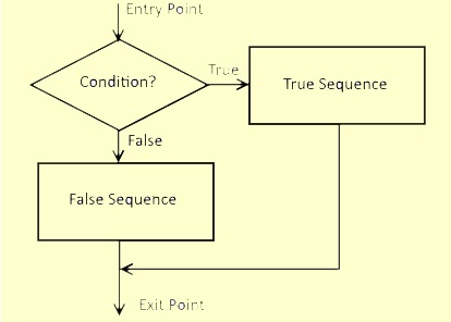
Selection structure provides a way for different code sequences to be executed depending on a logical or arithmetic condition. It is easier to see the possible structures using flow charts. The two-way selection structure is shown in the flow chart below. Based on whether the condition is True or False, one of two possible code sequences is executed. Note that after each sequence, flow control returns to one and only one "Exit Point". Not paying attention to this detail could result in the program drifting off into two completely different directions and creating undesirable spaghetti code.
| TWO-WAY SELECTION |
|
|
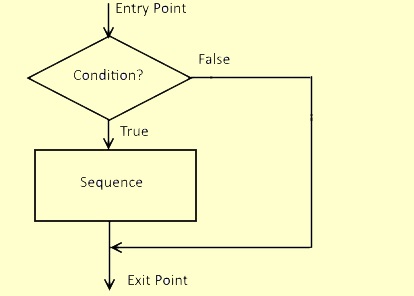
One way selection is another common structure and is shown below. In this case, only one condition, either True or False executes a code sequence. The other condition simply passes flow control around the sequence to the exit point.
| ONE-WAY SELECTION |
 |
We will use a couple of short programs to explores both selection structures.
Try it !
Example 2. Enter the test code below to explore two way selection based on a logical operation. Note that the semicolon will be used from this point forward to indicate that characters that follow it on a line of code are comment only and will be ignored otherwise. Later, when we use assembly language, the semicolon will be similarly recognized for creating comments.
;
; START
;
000 000 333 IN A ;Sense SwitchesgA
000 001 377
;Port 255 = 377Q
;
; ENTRY
;
000 002 UUU
;Mask
000 003 VVV
;Masking Pattern Data
000 004 XXX
;Arithmetic or Logical Operation
000 005 YYY
;Operation Data
000 006 ZZZ J-- True ;Conditional branch to TRUE SEQUENCE
000 007 016 True Location
000 010 000 True Page
;
; FALSE SEQUENCE
;
000 011 076 MVI A,'F'
;ASCII F (False)gA
000 012 106 ;
ASCII F
000 013 303
JMP ;Unconditional branch to EXIT
000 014 020
;Exit Location
000 015 000
;Exit Page
;
; TRUE SEQUENCE
;
000 016 076 MVI A,'T'
;ASCII T (True)gA
000 017 124
;ASCII T
;
; EXIT
;
000 020 323 OUT A
;AgData LEDs
000 021 377
;Port 255 = 377Q
000 022 303 JMP
;Unconditional branch to start
000 023 000
;Start Location
000 024 000
;Start Page
We will use the test code this way:
From the table below, enter the mask and arithmetical or logical operation and its associated data byte. Use NOPs where no instruction is needed.
Set the sense switches to zero, click RESET, and RUN.
Try various combinations of sense switch selections that include both true and false selections.
Observe the data LEDs display and note whether the expected value T or F ASCII code appears.
Note that the JMP 000 000Q causes the program to execute repeatedly (loop) so that we can observe changes without having to RESET and RUN again and again.
First, let's look at logical operations that test bits.
| IF (Condition) | Mask Code | Test Code | JUMP | Expected Result |
| D6 = 0 | None | ANI 100Q | JZ | 'T' displayed only if bit D6 is zero. No other bits should influence the result. |
| D6 != 0 | None | ANI 100Q | JNZ | 'T' displayed only if bit D6 is not zero. No other bits should influence the result. |
| (D6 or D4) = 1 | None | ANI 120Q | JNZ | 'T' displayed if D6, D4. or both are one. No other bits should influence the result. |
| (D6 or D4) = 0 | ANI 120Q | XRI 120Q | JZ | 'T' displayed if either D6 or D4 is zero. No other bits should influence the result. |
| (D6 and D4) = 0 | None | ANI 120Q | JZ | 'T' displayed only if both D6 and D4 are zero. No other bits should influence the result. |
| (D6 and D4) = 1 | ANI 120Q | XRI 120Q | JNZ | 'T' displayed only if D6 and D4 are 1. No other bits should influence the result. |
| Any bit = 1 | None | ORA A | JNZ | 'T' displayed if any bit (D0 to D7) is not zero. Note this requires only a one byte instruction. |
| All bits = 0 | None | ORA A | JZ | 'T' displayed only if all bits (D0 to D7) are zero. Note this requires only a one byte instruction. |
Selection structure does not always require two distinct branches and sequences of code. In these situations, one way selection can produce more efficient code. Let's look at a couple of examples to illustrate.
Example 3. When the only difference in the true/false selection is the value loaded into a register, a one way structure is possible. We simply load the register with the true selection just before testing for the condition and jumping to the exit if the comparison is true. If it is not, the register is loaded with the false selection before exiting.. Looking back at Example 1, we don't really need a true sequence if we preload the A register with an ASCII 'T' before the comparison is made. Let's recode it as a one way selection.
;
; START
;
000 000 333 IN A ;Sense SwitchesgA
000 001 377
;Port 255 = 377Q
;
; ENTRY
;
000 002 UUU
;Mask
000 003 VVV
;Masking Data
000 004 XXX
;Arithmetic or Logical Operation
000 005 YYY
;Operation Data
000 006 076 MVI A,'F'
;ASCII F (False)gA
000 007
106 ;ASCII F
000 010 ZZZ J-- EXIT
;Conditional branch on false to EXIT (do nothing)
000 011
015
;Exit Location
000 012 000
;Exit Page
;
; TRUE SEQUENCE (do something)
;
000 013 076 MVI A,'T'
;ASCII T (False)gA
000 014
124
;ASCII T
;
; EXIT (& do nothing)
;
000 015 323
OUT A ;AgData LEDs
000 016 377
;Port 255 = 377Q
000 017 303 JMP
;Unconditional branch to start
000 020 000
;Start Location
000 021 000
;Start Page
Note that we have eliminated 3 bytes of a JMP instruction and made the code
easier to follow. Keep in mind this only works because the MOV family of
instructions (specifically the MVI A instruction) does not affect status
bits.
Enter the modified code and make a few test runs to verify the results are the same as before.
Arithmetic Branching with the Intel 8080
Now let's try our hand at conditional branching based on arithmetic. Recall that all Intel 8080 arithmetic operations affect the status byte and thus can be used in conditioal branching. Comparing numeric values is frequently used to implement a conditional test. The SUB and SBI instructions are ideal for this. SUB and SBI affect the A register, which might be perfectly fine. In cases where we want the value of A preserved, the Intel 8080 has CMP and CPI instructions that perform the same operation as SUB and SBI respectively but leave the A register unchanged.
CMP r Subtract contents of register r to A
The
contents of register r is subtracted from the value in
A. A is unchanged The octal code byte for CMP is 27r. For example, ADD H
is 274Q.
Status bits affected
- Carry, Sign, Zero, Parity, Auxiliary Carry
CPI v Subtract immediate v from A v is subtracted from the value in
A. A is unchanged. The code for CPI is 376Q.
Status bits affected
- Carry, Sign, Zero, Parity, Auxiliary Carry
We commonly think of numeric comparisons and apply them in algebraic terms using the symbols "<" less than, ">" greater than, "=" equal to, and various combinations of these. With the Intel 8080, we have Z, NZ, C, and NC status bits. In simple cases, we can think through the problem and build the selection code needed. But for those more difficult situations, we can use a bit of basic algebra to help. Consider the table below.
| Algebraic Condition Table | |
| Algebraic Inequality | True Condition |
| = 0 | Z |
| != 0 or <>0 | NZ |
| < 0 | C |
| >= 0 | NC |
To build the selection code, write down the comparison as an algebraic inequality. Then use standard algebraic rules to manipulate the inequality until right hand side looks the same as one of the "Algebraic Inequality" entries. The remaining left hand side of the algebraic inequality is the arithmetic calculation we implement in code. The corresponding "True Condition" suggests the conditional jump instruction for the true sequence selection.
Suppose we have two values A and B and that we are wanting to do something on the condition that A<=B. The current form does not match a entry, so we perform the following algebraic steps:
A - B <= 0
Subtract B from both sides of the equation
(1) * (A - B) >= -1 * 0 Multiply both sides of the equation by
-1. Note that this reverses the inequality.
B - A >= 0
We now have ">=0" that's in the table. So we put B in register A, subtract (SUB) B or compare to B, and JNC to the true sequence. Or, we could JC around the true sequence.
Try it !
Example 4. Assume that the B register is loaded with 120. We will create several two way selection scenarios comparing the value in the A register with B. Enter the code below initially with NOPs in the "Compare Code" bytes. We will fill them in later.
;
; START
;
000 000 333 IN A
;Sense SwitchesgA
000 001 377
;Port 255 = 377Q
000 002 006 MVI B, 120 ;120gB
000 003 170
;20 = 170Q
;
; ENTRY
;
000 004 000 NOP
;Compare code
000 005 000 NOP
;Compare code
000 006 000 NOP
;Compare code
000 007 000 NOP
;Compare code
000 010 ZZZ J-- True
;Conditional branch to TRUE SEQUENCE
000 011 016
;TRUE SEQUENCE Location
000 012 000
;TRUE SEQUENCE Page
;
; FALSE SEQUENCE
;
000 013 076 MVI A,'F'
;ASCII F (False)gA
000 014 106
;ASCII F
000 015 303 JMP
;Unconditional branch to EXIT
000 016 020
;Exit Location
000 017 000
;Exit Page
;
; TRUE SEQUENCE
;
000 020 076 MVI A,'T'
;ASCII T (True)gA
000 021 124
;ASCII T
;
; EXIT
;
000 022 323 OUT A ; AgData LEDs
000 023 377
;
Port 255 = 377Q
000 024 303 JMP
;Unconditional branch to start
000 025 000
;Start Location
000 026 000
;Start Page
a. Algebraic condition: A=B. Checking for equal values in two registers is straightforward. Subtracting B from both side, we have A-B=0 that matches the first entry in the "Algebraic Condition Table". To calculate A-B, we could use SUB B or CMP B. Let's use CMP B to preserve the value in A. Referring to the chart, we will use JZ as the branching instruction. (For something as simple as is A equal to B, the CMP B and jump on zero is pretty obvious. For more complex inequalities, however, the longer algebraic method could prove useful.) Try the code below. Use the sense switches to enter various values for A and test that only when the value in the sense switches equals 120 (170Q) will the true condition (ASCII T) show in the data LEDS.
000 004 000
NOP ;Compare code
000 005 000 NOP
;Compare code
000 006 000 NOP
;Compare code
000 007 270 CMP B
;Compare A to B
000 010 312 JZ True ;Conditional branch to TRUE SEQUENCE
000 011 016
;TRUE SEQUENCE Location
000 012 000
;TRUE SEQUENCE Page
b. Algebraic condition: A!=B. Checking for not equal register values is also simple. The second table entry is used so we merely JNZ for JZ in the above. Make the change and test it as before. The true condition (ASCII T) should show in the data LEDs when the sense switches are set to values other than 120 (170Q).
c. Algebraic condition: A<B. This case is not quite so obvious, so let's use a little algebra to point to the solution. Looking back at the Algebraic Condition Table, we want the right side of the inequality to look like <0. To do this we subtract B from both sides and get A-B<0. This suggests that we compare A to B (CMP B) and use JC for the true selection. Make this change to the test code and verify that only when A is less that 120 (170Q) does the true condition (ASCII T) show in the data LEDs.
d. Algebraic condition: A<=B. For this case we need to get to >=0 in the table. Subtracting B from both sides yields A-B<=0, which is not quite right. Here we use the algebra inequality rule "Multiplying both sides of an inequality by -1 reversing the inequality sign". Thus we have (-1)*(A-B)=-A+B<=-1*0=0 or B-A>=0. To implement the left hand expression, we must first switch A and B values using the C register as temporary storage. CMP B and JNC completes the code required. Here's the code to substitute above and try. Only when the value entered in the sense switches is less than or equal 120 (170Q) should the true condition show in the data LEDs.
000 004 117
MOV C,A ;AgC
000 005 170 MOV A,B
;BgA
000 006 101 MOV B,C
;CgB
000 007 270 CMP B
;Compare A to B
000 010 322 JNC True
;Conditional branch to TRUE SEQUENCE
000 011 016
;TRUE SEQUENCE Location
000 012 000
;TRUE SEQUENCE Page
Armed with this knowledge, we should be able to tackle any arithmetic condition for which we have the code to perform the calculation.
Example 5. To try our hand at one way arithmetic selection, consider this simple task. Suppose that the A and B registers contain values and we want to keep the larger always in A. That is, if A>=B, we do nothing. If A<B, we will switch A and B.
;
; START
;
000 000 333 IN A
;Sense SwitchesgA
000 001 377
;Port 255 = 377Q
000 002 006 MVI, 120
;120gB
000 003 170
;120 = 170Q
;
; ENTRY;
000 004 270
;A>=B?
000 005 322 JNC EXIT ;Conditional
branch to EXIT
000 006 013
;Exit Location
000 007 000
;Exit Page
;
; FALSE SEQUENCE
(SWITCH A AND B USING C AS TEMPORARY REGISTER)
;
000 010
117 MOV C,A ;AgC
000 011 170 MOV
A,B ;BgA
000 012 101 MOV B,C
;CgB
;
; EXIT
;
000 013 323 OUT A ; AgData LEDs
000 014 377
;Port 255 = 377Q
000 015 303 JMP
;Unconditional branch to start
000 016 000
;Start Location
000 017 000
;Start Page
So long as A is greater than or equal B's value 120, execution continues at the
exit point. For A less than 120, A and B are swapped. before exiting.
Enter the code and try value above and below 120 to verify the program's operation.
Example 6. A good example of using selective structure is conversion of binary to hexadecimal ASCII notation. For binary values 0 to 9, conversion requires adding 48 to get the ASCII code for numeric digits '0' to '9'. For binary values 10 to 15, we must add 55 to get alphabetic characters 'A' to 'F' . This can be coded in two different ways.
Use two way structure: Test if the binary value exceeds 9. If so, we would add 55; if not, we would add 48. Enter the code below and test by setting the sense switches to values from 0 to 15 and checking that the Data LEDs show the correct hex value from 0 to F.
;
; START
;
000 000 333 IN A
;Sense SwitchesgA
000 001 377
;Port 255 = 377Q
000 002 376 CPI, 10
;A>=10?
000 003 012 ;10 =
012Q
000 004 322 JNC TRUE ;If
so, branch to TRUE SEQUENCE and add 55
000 005 014
;TRUE SEQUENCE Location
000 006 000
;TRUE SEQUENCE Page
;
; FALSE SEQUENCE
;
000 007 306 ADD 48
;A+48gA
000 010
060 ;48
= 060Q
000 011 303 JMP EXIT ;
REPEAT
000 012 016
;EXIT Location
000 013 000
;EXIT Page
;
; TRUE SEQUENCE
;
000
014 306 ADD 55
;A+55gA
000 015 067
;55 = 067Q
;
; EXIT
;
000 016 323 OUT
A ;AgData
LEDs
000 017 377
;PORT 255 = 377Q
000 020 303 JMP START
;REPEAT
000 021 000
;START Location
000 022 000
;START Page
Using one way structure: Add 48. Test if the result is less than 57. If so, do nothing; if not, add 7. Enter the code below and test by setting the sense switches to values from 0 to 15 and checking that the Data LEDs show the correct hex value from 0 to F.
;
; START
;
000 000 333 IN A
;Sense SwitchesgA
000 001 377
;Port 255 = 377Q
000 002 306 ADD 48
;A+48gA
000 003 060 ;48
= 060Q
000 004 376 CPI, 57
;A<57?
000 005 071 ;57 =
071Q
000 006 332 JC EXIT
;If so, branch to EXIT
000 007 013
;Exit Location
000 010 000
;Exit
Page
;
; FALSE SEQUENCE
;
000 011 306 ADD 7
;A+7gA
000 012 007
;7 = 007Q
;
; EXIT
;
000 013 323 OUT
A ;AgData
LEDs
000 014 377
;PORT 255 = 377Q
000 015 303 JMP START
;REPEAT
000 016 000
;START Location
000 017 000
;START Page
Continue to next Experiment - Click Here