Experiment 5 - Iteration
So far we have explored programming structures sequence and selection. Our programs can perform step-by-step tasks including different steps based on conditions encountered during execution. While these are powerful capabilities, many common tasks are repetitive in nature and involve execution of a block of code multiple times. To add this capability, we will use a branching instruction to loop back and re-execute the block of code to be repeated. Each execution of this code is called an iteration from which we get the name iteration structure. Of course there has to be some way to end the iterations. This is done by making the loop-back conditional; that is, the loop-back ceases when a condition is met.
An iterative structure is also known as a loop because (as we noted above) the code loops back to an earlier instruction to repeat a block of code. Three types of iterative structures commonly found in programs are: the WAIT-DO LOOP (also called a polling loop), the WHILE-DO LOOP (also called a pre-test loop) and the DO-WHILE LOOP (also called a post-test loop). We will describe each loop type and give an example.
Basic iterative Structures - The WAIT-DO LOOP
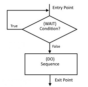
The flow chart for an example WAIT-DO LOOP is shown below.
| WAIT-DO LOOP |
|
|
The WAIT-DO LOOP is a polling loop. The program sits in a tight, do nothing loop until the WAIT a condition is met or not met as the case may be. The flowchart shown loops while the condition is true and "breaks free" when the condition becomes false. Of course, the wait condition could just as easily be based on false looping and true to move on.
Example applications are simple I/O routines in which the processor waits for a device to be ready before receiving/sending data. Typically, a status bit on a I/O port is tested (polled) and as long as the WAIT condition exists, the code loops and tests again. When the WAIT condition no longer exists, the DO sequence is executed and data is received or sent. Having to wait around for an I/O device to be ready is not the most effective way to handle external devices. Click here for a discussion of this topic. The example below uses polling to echo characters to our RDT.
TIME OUT!
We are reaching the point that hand coding begins to be burdensome. It's time we looked into using an Intel 8080 assembler program that will produce the Intel 8080 executable code without hand coding.
Finding an Intel 8080 assembler is not easy. Fortunately, an online Intel 8080 assembler is currently available for our use. Click here for full documentation of the ZASM assembler. Below is a quick start guide. We will use the next example to learn how to use the ZASM assembler.
A program written in assembly code is called source code. It is a text file with no hidden formatting characters (except the tab). To edit such a file, we need a true text editor not a word processor. A good example is Notepad++ available here. Once the source file (type "asm") is ready to assemble, the ZASM assembler will take it and produce an Intel HEX (.hex) file that can be loaded directly into the WhippleWay Emulator's memory for execution. No more flipping switches or reading Data LED's!
The steps that may be required to prepare a program for use with the ZASM assembler are outlined below.
After the source code has been properly prepared , follow this procedure to assemble, load, and run a program in the WhippleWay Emulator.
This may seem like a lot of work, but you will soon agree that it is a great improvement over hand coding and loading. With a little set up and getting "used to", the procedure will go fast. For instance, set Notepad++ as the default editor for "asm" and "hex" files. Use the "Alt Tab" keyboard keys to switch between Notepad++, the WhippleWay Emulator, and the ZASM assembler.
Now back to the first example.
Try it!
Note: Rather than use an inline version of the Front Panel 8080 from this point on, opening a new window works better. Click here and then return to this page.
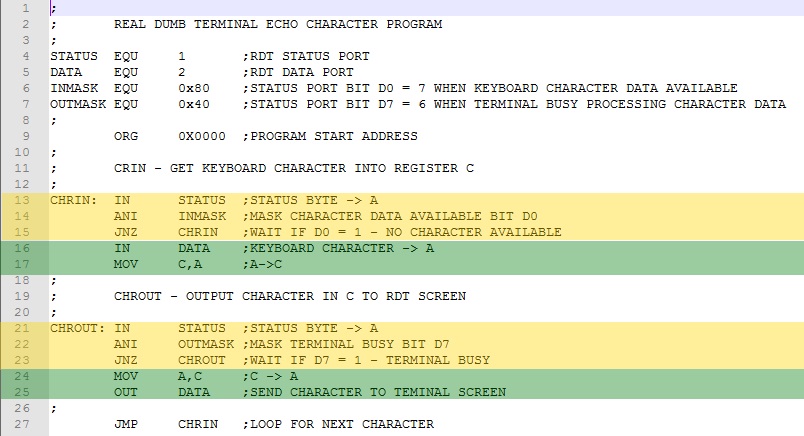
Example 1. Terminal input/output provides a good example of how to use a WAIT-DO LOOP. The code below outputs a character typed on the RDT.
A common way for external devices to communicate with the processor is through a pair of I/O ports, one for status and the other for data. The status port is read using an IN instruction to determine if the device has data ready for receiving or is able to accept data for sending. The data port is then used to receive data with an IN instruction or send data using an OUT instruction.
The WAIT condition code is highlighted in yellow. The DO code sequence is highlighted in green.
Recall that the Intel 8080 IN and OUT instructions can address up to 256 I/O ports. For the RDT, the status port is 1 and data port is 2. Rather than use the numeric values directly in the IN/OUT instructions, we use the ZASM EQU pseudo instruction to define constant values using the labels STATUS and DATA. This serves two purposes. First, using descriptive words helps make the code self-documenting, which could prove useful when later revisiting the code or if another person is studying the code. Second, should the status or data port change, we would only have to make the change once in EQU statements. Note that we also labeled constant values for the input status mask (INMASK) and the output status mask (OUTMASK).
The RDT keyboard status bit is D7. When this bit is zero, a keyboard character is available for input. The ANI mask to test D7 is INMASK whose value is 0b10000000 (line 14). The JNZ instruction (line 15) loops until a zero in bit D7 (data available) is detected, then the IN statement is executed loading the keyboard character into the A register (line 16).
Similarly, the output status port is checked for a busy condition and, while detected, the program waits in a loop (lines 21-23). When not busy (D6=0), an OUT (line 25) sends the contents of A to the RDT window. Note that the C register is used to hold the inputted character while send status is being tested. Otherwise, the character to be output would be overwritten and lost!
Download the ECHO Program source here; the n assemble and test with the RTD.
Note: Always left click while hovering in the double red border of the RDT before typing characters on the keyboard.
With the 50 ms clock cycle selected, typing speed is limited. A key press could be missed while the emulator is processing a previous key entry. Changing to Full Speed eliminates this issue.
Basic iterative Structures - The WHILE-DO LOOP
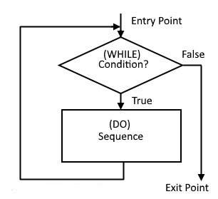
Like the WAIT-DO LOOP, the WHILE-DO LOOP checks the condition first. They differ in that the WHILE-DO LOOP performs the DO sequence while the condition is True. An example WHILE-DO structure is shown below next to a WAIT-DO structure.
| WHILE-DO LOOP | WAIT-DO LOOP |
 |
|
Since, by pre-testing, the DO sequence may never be executed, the WHILE-DO structure is suitable for tasks that involve zero or more repetitions (0+ task). Here is an example of a 0+ task.
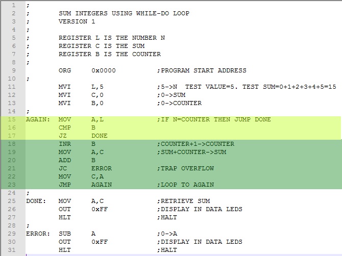
Example 2. Sum the consecutive integers from 0 to N where N is equal to or greater than zero.
In developing a computer solution to this problem, a good place to start is to literally follow the steps if solving by hand. This does not always produce the most compact and efficient code, but once we have a working program, we can look for ways to make improvements. With this in mind, we reason as follows:
The given task utilizes three integer values; namely, the maximum number N; a counter (0, 1, ..., N); and an accumulated sum. Let's use the L register to store the maximum number N; the B register to store the counter; and the C register to store the sum . Keep in mind that utilizing Intel 8080 8-bit registers imposes the constraint that the maximum value for any integer value will be 255. For instance, the sum (C register) will overflow for a value of N = 23. Also, when the Intel 8080 powers up, we can't be sure of register values, so we have to initialize them. Let's initialize the B register (the counter) and the C register (the sum) to zero. The L register (N) is set to whatever maximum value we choose. If we assume the sum is zero for the case N=0, then the DO sequence need not be executed to give the correct result (sum = 0). This then is a 0+ iteration case and the WHILE-DO LOOP is an appropriate structure. As long as the L register (N) is not equal to the B register (the counter), we execute the DO sequence incrementing the counter and accumulating the sum. When L equals B (the counter reaches N), the loop is exited with the result in the C register (the sum). The code below follows these steps with N=5 for testing.
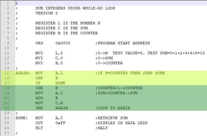
We first initialize the registers (lines 11-13). For N=5, the test sum is 1+2+3+4+5=15. The WHILE condition (highlighted in yellow) checks to see if the counter (B register) has reached the maximum value N (L register). The DO sequence (highlighted in green) increments the counter (B register) and accumulates the sum (C register). When the counter (B register) has reached the maximum value N (L register), the sum (C register) is moved to A and displayed in the Data LEDs (lines 24-25) .
Download this version program here. Assemble and test it. Try different values for N. From math, the test sums can be calculated using the formula N*(N+1)/2.
Try N=23. The display shows 20 (0x14) , not the correct answer 276. The A register has overflowed during the ADD B instruction. We can trap this error by inserting a jump on carry instruction (JC) after line 21, the ADD B instruction. Below is the modified version of our program.
The WHILE condition is highlighted in yellow. The DO sequence in each case is highlighted in green.
The jump on carry instruction has been added at line 21 along with error code at the ERROR label. Download this version of the program here. Assemble and test it. Values of N>=23 will be trapped and diverted to ERROR.
The program is fine as it is, but we could refine it a bit should we choose. For instance, by summing a decrementing N, we could eliminate the counter. This would be the same as calculating the sum backwards; i.e., 5+4+3+2+1+0=15. This also would allow us to simplify the WHILE condition by merely checking for N=0 as it is decremented. Here is the modified program.
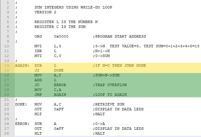
The WHILE condition is highlighted in yellow. The DO sequence in each case is highlighted in green.
Download this version of the program here. Assemble and test it.
Note that while we have shortened and simplified the program, its logic is not as easy to understand. Unless program space and/or speed are considerations, sometimes it is preferable to stay with the most literal and easily understood solution!
Basic iterative Structures - The DO-WHILE LOOP
An example DO-WHILE flow chart is shown on the left below with the previously described WHILE-DO to the right.
| DO-WHILE LOOP | WHILE-DO LOOP |
 |
|
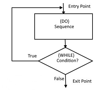
The essential difference between DO-WHILE and WHILE-DO loops is that the former executes the DO sequence once before the condition is tested while the latter tests first and may not execute the sequence at all. This makes the DO-WHILE useful for tasks that involve at least one iteration, 1+ tasks. Here is an example.
Example 3. Using the Data LEDs, make a right-to-left chasing light display.
Turning LEDs on and off in a repeating pattern is a 1+ task because the program starts by turning on the first LED. Thus, it is a good candidate for a DO-WHILE iterative structure. Here's a first try at a program.
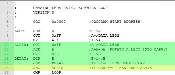
The DO sequence in each case is highlighted in green. The WHILE condition is highlighted in yellow.
To start, we turn off all LEDs (line 7-8). Then we start by setting the right most bit of the A register to one (line 9). The DO sequence (lines 10-14) outputs the A register turning on the right-most LED. Then we rotate the bit to the left with a ADD A (multiply by 2) instruction (line 11). We introduce a delay to slow down the rotation by counting down to zero a pre-set value (line 12) in the B register. Note that the DCR B instruction (line 13) does not affect the carry bit. The WHILE condition (line 15) checks to see if the bit has rotated through all eight positions and has reached the carry. Until this happens, we simply repeat the DO sequence. Download this version of the program here. Assemble and test it.
Suppose we had wanted the LEDs to chase from left to right? We need a right rotation instruction. The Intel 8080 has a complete set of rotation instructions, both right and left. See below.
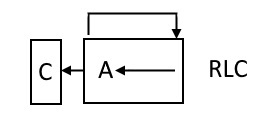
RLC Rotate accumulator left The carry bit is
set equal to the high-order bit of the accumulator. The contents of the
accumulator is rotated one bit position to the left, with the high order bit
being transferred to the low-order bit position of the accumulator. The code byte for
RLC is 007Q.
Status bits affected
- Carry
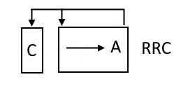
RRC Rotate accumulator right
The carry bit is set equal to the low-order bit of the accumulator. The contents
of the accumulator is rotated one bit position to the right, with the low-order
bit being transferred to the high-order bit position of the accumulator. The code byte for
RRC is 017Q.
Status bits affected
- Carry
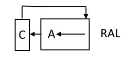
RAL Rotate accumulator left through carry
The contents of the accumulator is rotated one bit position to the left.
The high-order bit of the accumulator replaces the Carry bit, while the Carry
bit replaces the high-order bit of the accumulator. The code byte for RAL is
027Q.
Status bits affected
- Carry
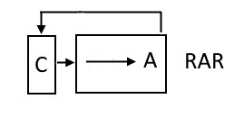
RAR Rotate accumulator right through carry
The contents of the accumulator is rotated one bit position to the right. The
low-order bit of the accumulator replaces the carry bit, while the carry bit
replaces the high-order bit of the accumulator. The code byte for RAL is
037Q.
Status bits affected
- Carry
The changes to our Chasing LED program are minor. The initial LED to light is the left most, so we must change line 9 to 0b10000000. Instead of ADD A, we substitute RAR to rotate right into carry. Here's the modified code.
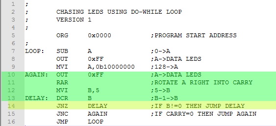
The DO sequence in each case is highlighted in green. The WHILE condition is highlighted in yellow.
Download this version of the program here. Assemble and test it.
Continue to next Experiment - Click Here