Experiment 6 - Memory Access
Up to this point our programs have been simple enough that the number of data values could be accommodated by the Intel 8080's seven working registers. As more complex tasks and programs are developed, the number of data values will likely exceed seven and we will need to use the computer's memory for additional storage. In this experiment we will learn how to access memory and greatly increase the processor's computing power.
Direct Memory Addressing
If we need to save and retrieve one or two data values in memory, the Intel 8080 provides a solution called "direct addressing". The store accumulator direct (STA) and load accumulator direct (LDA) provide a way save/retrieve a single byte of data to/from memory. STA and LDA are three byte instructions. The first is the code byte; the second two bytes form the direct memory address. The order of the address bytes is first location then page. For example, STA 001 200Q would be 062 200 001. The contents of A would be store at address 001 200Q.
STA a Store A Direct The contents of accumulator A replaces the byte at memory address a. The code byte for STA is
062Q and is followed by the location of address a and the page of address a.
Status bits affected - None
LDA a Load A Direct The byte at memory address a replaces the
contents of the accumulator A. The code byte for LDA is 072Q and is followed by the
location of address a and the page of address a.
Status bits affected - None
The store HL direct (SHLD) and load HL direct (LHLD) instructions provide a way to save/retrieve two bytes of data to/from memory. SHLD and LHLD are three byte instructions. The first is the code byte; the second two bytes form the direct memory address where L will be stored and loaded. H is stored and loaded at the next memory address. The order of the address bytes is first location then page. For example, LHLD 001 200Q would be 052 200 001. Register L would be loaded from 001 200Q and H from 001 201Q. The exchange HL and DE (XCHG) instruction makes it convenient to store and load registers D and E directly; that is, use XCHG then SHLD to store DE or LHLD then XCHG to load DE.
SHLD a Store H and L Direct The contents of the L register
replaces the byte at the memory address a and H replaces the byte at memory address
a + 1. The code byte for SHLD is 042Q and is followed by
the location of address a and the page of address a.
Status bits affected - None
LHLD a Load H and L Direct The byte at memory address a
replaces the contents of the L register and the byte at memory address
a + 1 replaces the contents of H register. The code byte for LHLD is 052Q and is
followed by the location of address a and the page of address a.
Status bits affected - None
XCHG Exchange registers The 16 bits of data held in the Hand L
registers are exchanged with the 16 bits of data held in the D and E registers. The code byte for
XCHG is 353Q.
Status bits affected - None
As we begin to explore storing and loading data in memory, we must remember that program and data share the same Intel 8080 memory space. It is good practice to create separate blocks or segments of memory for the program and data. Generally, we start with the program segment and follow with the data segment.
Try it!
Note: Rather than use an inline version of the Front Panel 8080 from this point on, opening a new window works better. Click here and then return to this page.
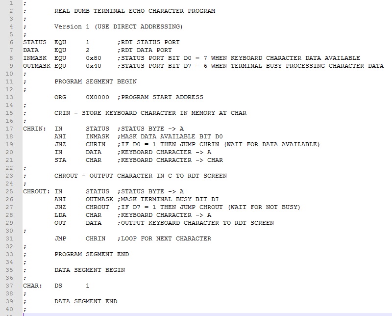
Example 1. Recall that in the RDT Echo Program from Experiment 4 we saved the keyboard character in the C register while polling the I/O status byte. Rather than using a register to store the character, let's use direct memory addressing to store it in memory instead.
Here is the modified RDT Echo Program.
The program segment starts at the beginning of memory with data segment immediately following. The ZASM pseudo instruction "DS" (short for Declare Storage) sets aside 1 byte of data memory labeled as "CHAR". In line 21, the inputted keyboard character is temporarily stored at CHAR using the STA instruction and laterat line 28 loaded with the LDA instruction for outputting.
Download this version of the program here. Assemble and test it.
Take a look at the ZASM assembler list file (RDT_ECHO.lst). It shows the addresses for the program instructions and data. CHAR, for instance, is at address 0x001B. Note that the assembler by default makes the initial contents of this DS memory address 0xFF. If some other initial value is desired, simply include it as a second parameter following the number of bytes declared. For instance, "CHAR: DS 10, 0x00" creates a data segment of ten bytes, each a zero. After testing the program, stop the emulator and examine 0x001B. The contents should be the last keyboard character typed.
Example 2. Assume that two 16-bit values are stored in memory. The first is the base (beginning) address of a memory array. The second value is the bias that, when added to the base address, gives the address of the array data byte. Write a program that calculates the address of the data byte.
To access and process double byte unsigned values, we will use HL direct addressing. Here's the finished program.
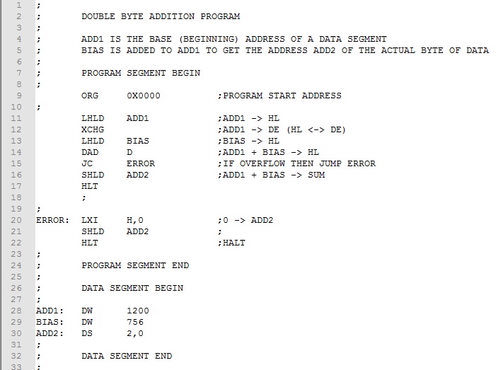
We use the ZASM pseudo instruction DW (Declare Word) to store the values to be added (lines 28-29)). LHLD loads HL, the base address then XCHG switches it to DE (lines 11-12). HL is now free to load the bias again using LHLD (line 13). The DAD D adds the base address and bias and stores it at ADD2 using the SHLD instruction (lines 14-16). We could use the address stored at ADD2 to access the array data byte.
Recall that DAD sets the carry if an overflow occurs. This would occur if, after adding the bias, the result exceeded 65,535 that is beyond the limits of Intel 8080 memory. We use the JC (line 15) to trap an unsigned number error.
Download this version of the program here. Assemble and test it. Use the ZASM list file to check that the sum is 1200 + 756 = 1956 or 0x07A4. Note that for DW and the Intel 8080 double byte instructions, the first byte is the location (lower) byte and the second is the page (upper) byte.
Indirect Memory Addressing
The ability to access one or two bytes of memory directly is useful, but the real power of computing comes from being able to access blocks containing many bytes of memory. This would enable us to process large amounts of data in lists and tables using relatively simple iterative structures. The Intel 8080 uses register pairs B and C (BC); D and E (DE); and H and L (HL) to indirectly address memory locations. By setting registers B, D, or H to the address page (upper byte of address) and C, E, and L to the address location (lower byte of address), we can access all 65,536 bytes of Intel 8080 memory.
The most versatile indirect addressing method uses the HL register pair. The byte in memory pointed to by the address in HL becomes "the memory register" designated as M. All instructions that apply to other working registers function exactly the same with M. For example, MOV A,M moves the contents of memory byte addressed by HL into A. ADD A,M adds the contents of the memory byte addressed by HL to A. In effect, the memory byte addressed become a working register. Operations are slower because of the additional memory accesses, but otherwise, everything is the same.
Register pairs BC and DE can also be used for indirect addressing though in a more limited way. For these register pairs, store accumulator (STAX rp) and load accumulator (LDAX rp) instructions work like STA and LDA except the address is contained in rp (either BC or DE) rather than immediately following the code byte as with STA and LDA. Working register operations with BC and DE are not possible.
Here are instructions useful for indirect addressing. For the parameter rp below, B alone designates register pair BC; D alone designates register pair DE; and H alone designates register pair HL.
LXI rp,a Load register pair immediate
The
contents of register pair rp is loaded with the two byte value v.
The octal code byte for LXI B is 001Q, for LXI D it is 021Q, and for LXI H it is
041Q The first data byte following the code byte is the lower byte
of address a and is loaded into C, E, or L respectively. The second data byte
following the code byte is the upper byte of address a and is loaded into B, D,
or H respectively. For example, LXI H, 1000
produces the three bytes 041Q, 350Q, 003Q and loads H with 003Q and L with 350Q.
Status bits affected - None
DAD rp Double add register
pair
The
contents of register pair rp is added to H and L with the result in H and L.
The octal code byte for DAD B is 111Q, for DAD D it is 031Q, and for DAD H it is
051Q.
Status bits affected - Carry
INX rp Increment register
pair
The
contents of register pair rp is incremented by 1. The octal code byte for
INX B is 003Q, for INX D it is 023Q, and for INX H it is 043Q.
Status bits affected - None
DCX rp Decrement register pair
The
contents of register pair rp is decremented by 1. The octal code byte for
INX B is 013Q, for INX D it is 033Q, and for INX H it is 053Q.
Status bits affected - None
STAX rp Store A indirect The contents of A replaces
the byte at the memory address in register pair rp (BC and DE only). The code byte for STAX B is
002Q and for STAX D it is 022Q.
Status bits affected - None
LDAX rp Load A indirect The contents of the memory
address in register pair rp (BC and DE only) replaces the contents of A. The code byte for
LDAX B is 012Q and for LDAX D it is 032Q.
Status bits affected - None
Two frequent applications of indirect addressing are list processing and table look-up. For list processing, we store data in consecutive bytes of data memory. After pointing a register pair to the first list item, we process it using indirect addressing instructions. We then point the register pair to next item in the list and repeat until the end of the list is reached.
Table look-up is a bit different. We store data in memory and access it using an numeric offset called an index. To look up something in the table, we supply the index and use to calculate the address of the corresponding data item. Indirect addressing instructions can he be used to access the data item..
Indirect Memory Addressing - Lists
A list is a simple data structure consisting of a sequence of individual items. Starting with the first item in the list, we process the items sequentially. Identifying when the end is reached is typically done in one of two ways. If we know the total number of items in the list, we can simply count the number processed and stop when the total is reached. We call this a "count-based" approach. The other way is to mark the end of the list with a sentinel value that is detectable and distinct from all legal data values. We call this a "sentinel-based" approach. Examples 3 and 4 below add a list of single byte integers stored in memory.
Example 3 uses a count-based approach since we know the exact count in advance.
For Example 4, we don't know the count. If we were adding only positive values, we could use zero or a negative value as the sentinel. Since all numeric values are allowed, specifying a sentinel value is not possible. We must fall back on a "count-based" approach using the assembler to calculate the count from the beginning and ending of the data segment.
Examples 5 and 6 use a sentinel-based approach to process an ASCII message. We use the unprintable ASCII Null (0x00) character as the sentinel value to mark the end of a message.
Try it!
Example 3. Sum the list of single byte integers (3,12,32,14,13,38,0, and -5) and display the total in the Data LEDs. Assume the number of integers to be summed is fixed at eight.
As already noted, we use a count-based approach in this example. Further, since the number of integers is known in advance and not zero, we have 1+ task and a DO-WHILE loop is appropriate. The basic approach is as follows: load a register with the count, decrement the register after each iteration, and output the result when the register reaches zero. We use the DB pseudo instruction to store the list of integers. Note that the assembler will correctly convert the negative integer (-5) using twos-complement arithmetic.
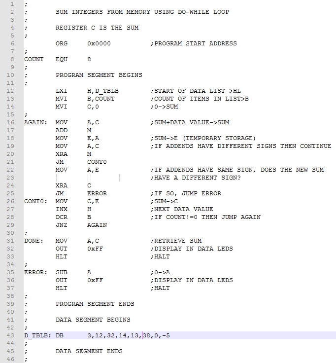
Register C accumulates the sum and register B holds the count. Lines 10-12 initialize C (the sum) to zero, B (the count) to eight, and the HL (the indirect addressing register pair) to D_TBLB (the beginning of the data list). Lines 14-25 are the DO-WHILE loop. The DO sequence (lines 14-23) accumulates in the sum in C using the M register to get values to be added. The WHILE condition (lines 28-29) is based on the decremented count in B. Lines 31-32 display the result in the Data LEDS.
Detecting overflow in lines 18-26 is not as simple as in the previous SUM_INTEGER program. There we were dealing with unsigned values and a simple jump on carry would detect an ADD overflow. Since the program here is adding twos complement numbers, the test for overflow is more complicated. We must apply these rules.
We use the exclusive-or instruction to check if the addends have a different sign. If so, we continue knowing no overflow has occurred. If the signs are the same, we again use the exclusive-or instruction to check the sign of the newly calculated sum is different from the addend signs. If so, an error is generated.
Download this version of the program here. Assemble and test it. The answer should be 107 or 153Q.
Change 32 and 38 to -32 and -38 respectively to get a negative result. Check by converting the result by complementing it and adding 1.
Try values that would overflow like 100 and 30 or -100 and -30. Also, try adding -100 and 30 that should not overflow. Remember to change the COUNT value in line 8 from eight to two!
Example 4. Sum the list of single byte integers (3,12,32,14,13,38,0, and -5) and display the total in the Data LEDs. Assume the number of integers is not fixed and there are fewer than 256.
The program is basically the same as Example 3 except the count of values to add is not known. We must count them before proceeding. By subtracting the beginning from the ending addresses of the list, we can determine the count. Of course, this assumes one-byte values. If the values were two byte, we would divide the count by 2 using a rotate right instruction. Once the count is determined, we load it in register B and proceed as before with one difference. Since the count is unknown and could be zero, we change to a WHILE-DO structure and test before doing any summing. Here is the program rearranged slightly from Example 3.
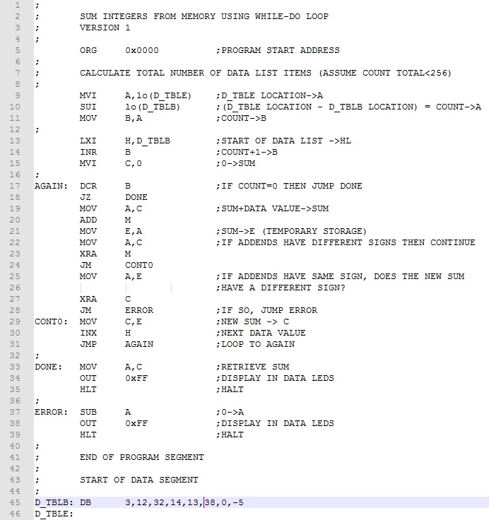
In lines 9-11 we calculate the number of integers in the list. Since the list is less than 256 values, we use single byte subtraction. Note the ZASM pseudo-name "lo" extracts the location (lower) byte from the address. Were it needed, "hi" would extract the page (upper) byte from the address. Rather than moving B to A each iteration and testing for zero, we increment B once in advance and use DCR B to count iterations down to zero.
Download this version of the program here. Assemble and test it. Testing this time, we won't have to worry with setting COUNT each time we change the list of data in the program!
Example 5. With the message "Hello World" in memory, output it to the RDT.
Storing and outputting messages or "strings of characters" is a common task in programming. Before tackling the code to output the message, we need to look at how we will store the message in memory and how to signal the end of the message. ZASM makes the storage of the message easy by using the pseudo instruction "DM" (short for Declare Message). The argument that follows DM is the message in single quotes, which in this case is 'Hello World'. At the beginning of the line is an appropriate label that we'll use to access the message with indirect addressing. As suggested previously, we can use unprintable ASCII Null (0x00) character as the sentinel value. One additional thought: Let's start the message by outputting a control-y character to clear the RDT window. Here's the program.
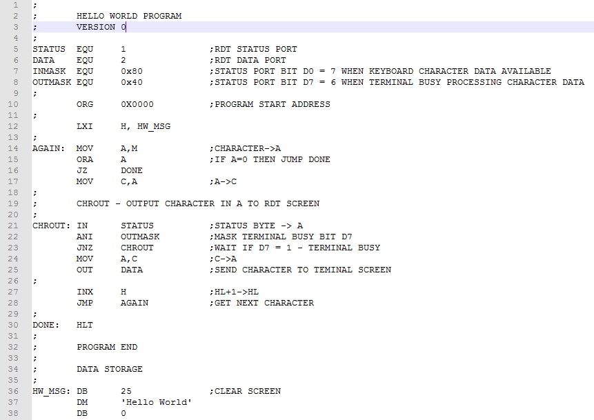
The message (clear screen character and message plus sentinel byte) are stored in memory using the DB and DM pseudo instructions respectively (lines 36-38). To prepare to output the message, we load HL with the starting address of the message, HW_MSG (line 12). We then set up a WHILE-DO loop to iterate through the characters of the message. The WHILE section tests for the sentinel byte (lines 14-16). The DO section loads the A register from the M register then uses the standard RDT output code to send the character to the terminal window (lines 17-25). We then point HL to the next character and do again (lines 27-28).
Download this version of the program here. Assemble and test it.
Example 6. Convert a message to upper case and store it at a new address in memory. Output both messages to the RDT window to verify that the program worked correctly.
To develop this program we first have to understand the difference between lower and upper case ASCII code. Let's take a look at the letters at the ends of the alphabet.
"a" is 0x61 or 0b01 100 001 "A" is 0x41 or 0b01 000 001
"z" is 0x7A or 0b01 111 010 "Z" is 0x5A or 0b01011010.
It would appear that the difference is bit 5; it is 0 for uppercase and 1 for lower case. So to convert alphabetic characters to upper case, we would simply clear (make zero) bit 5.
Because we are copying a message to a new location, we will need two register pairs, one to read text from memory and one to write modified text to memory. Let's use HL and the M register for reading and DE and STAX D for writing.
The main components of program are (1) convert the original message to upper case and copy to new location, (2) output the original message to the RDT window; and (3) output the revised message to the screen. Parts (2) and (3) require appropriate screen formatting for ease of viewing. Here's the finished program.
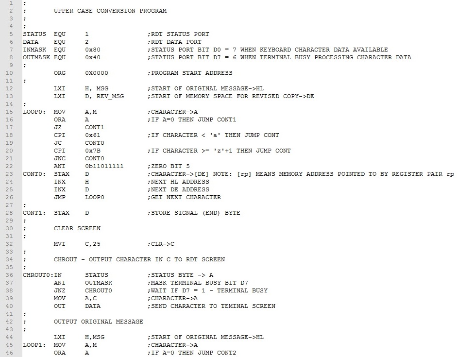

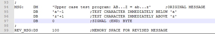
First we copy the original message to the memory reserved for the copied message (lines 15-28). The WHILE-DO loop structure is much like Example 2. The main difference is the test if register A is a lower case character (lines 18-22). If it is, an ANI 0b11011111 instruction (line 22) masks off (clears) bit 5 converting character to upper case. Otherwise, this ANI instruction is skipped. The other difference is the STAX D instruction stores the character in the memory reserved for the copied message (line 23). Finally, HL and DE are incremented and execution branches back to process the next character (lines 24-26). After the original message has been copied, a clear screen control character is output (lines 32-40) and the original message is output using essentially the same code as Example 2 (lines 44-55). Finally, a new line (CR and LF) are output (lines 59-71) and the revised message is output (lines 75-86).
Download this version of the program here. Assemble and test it. Note that the bytes in lines 95 and 96 are at the extreme ends of the lower case alphabet. Testing these assures that conversion does not extend beyond the bounds of "a" to "z". To test these bytes will require using the assembly listing and examining the addresses where these bytes will be copied.
Indirect Memory Addressing - Look-Up Tables
Look-up tables are useful in translating one piece of information to another. The table "index" is points to the piece of information in the table that we call the "result". Given the index, we can calculate the corresponding information in the table. Take for example the table below.
| Index | Result |
| 0 | 0 |
| 1 | 12 |
| 2 | 23 |
| 3 | 35 |
| 4 | 44 |
| 5 | 55 |
| 6 | 68 |
| 7 | 77 |
| 8 | 86 |
| 9 | 102 |
| 10 | 115 |
For each index item, there is one and only one result item. Typically, we are given the index and are asked to return the corresponding result. To create table look-up with the Intel 8080, we use indirect addressing. We place the table results in sequential memory, one byte per value. The beginning address of the table we call the "base" address. The simple formula below calculates the "result address".
Result Address = Table Base Address + Index
With the calculated "Result Address" in HL, MOV A,M loads the result into the A register ready for further processing. Unlike "list" processing, "look-up" table processing does not involve working our way through all the items of a list stored in memory. We only access (using indirect addressing) the item or items needed. Let's flesh this idea out more by looking out how this work using a couple of Intel 8080 examples.
Try it!
Example 7. Given the look-up table above, develop a program that reads the sense switches and displays the result value given in the table. Output a 0xFF for an index value greater than 10.
The program is simple enough. We will point HL to the base address of look-up table, read the sense switches, add this to the base address, load the result, and display it in the Data LEDs.
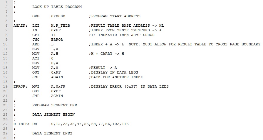
The result table is store in memory using the DB pseudo instruction (line 27. The base address of the table is labeled "R_TBLB". The HL register pair is initialized with this address (line 6). The sense switches load the index into A and the value checked for valid range (lines 7-9). The index (contents of A) is added to HL to determine the address of the look-up result (lines10-13). Note that a two-byte addition is implemented in case the look-up table crosses a page boundary. Finally, the result is moved to A and output to the Data LEDs (lines15-16).
Download this version of the program here. Assemble and test it.
When the result data is fixed length, as in this example, the calculation of the result address is simple. But suppose that this is not the case.
Example 8. Input a single digit (0-9) from the RDT keyboard and translate it into the equivalent word as shown in the table below.
| Index | Result |
| 0 | ZERO |
| 1 | ONE |
| 2 | TWO |
| 3 | THREE |
| 4 | FOUR |
| 5 | FIVE |
| 6 | SIX |
| 7 | SEVEN |
| 8 | EIGHT |
| 9 | NINE |
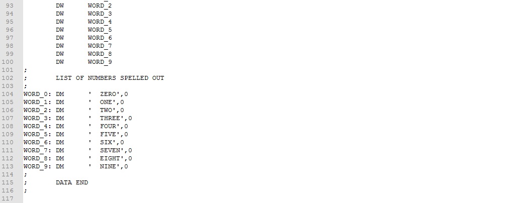
The integer values in the first column (index) points to words in the second column (result). Because the result data is not fixed length, we have to add an intermediate pointer address that is fixed length. Consider the modified table below.
| Index | Result Address | Result | |
| 0 | WORD_0 | ZERO | |
| 1 | WORD_1 | ONE | |
| 2 | WORD_2 | TWO | |
| 3 | WORD_3 | THREE | |
| 4 | WORD_4 | FOUR | |
| 5 | WORD_5 | FIVE | |
| 6 | WORD_6 | SIX | |
| 7 | WORD_7 | SEVEN | |
| 8 | WORD_8 | EIGHT | |
| 9 | WORD_9 | NINE |
The middle column is the address of the beginning of the word in the third column. Because the middle column is fixed length (two bytes each item), we can easily calculate the address of the result word using the following formula:
Address of Word message = Base Address of "Result Address" + Index * 2
Given an index value, the formula calculates the address of the message to be output. Take a look at the result.
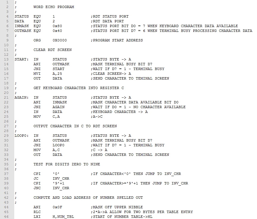
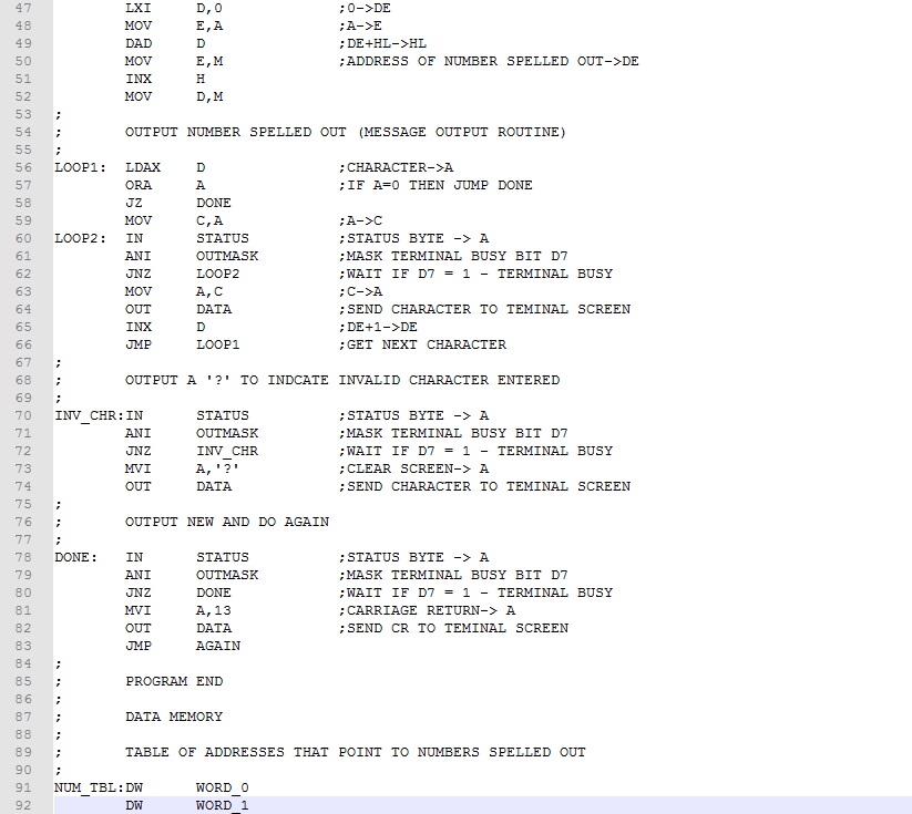
The first of the program is straightforward. The screen is cleared and a single character is input form the keyword (lines 15-35). If the character is a valid digit (lines 39-42), the ASCII digit is converted to binary integer (line 44). The address of the word pointer is calculated and stored in register pair DE (line 47-52). A simple message output routine takes it from here (lines 56-66).
Download this version of the program here. Assemble and test it.
Continue to next Experiment - Click Here