Experiment 7 - Optimizing for Speed and Size
We have experimented with many of the capabilities of the Intel 8080 without giving much thought to speed of execution or the size of the resulting program. For most of the programs so far, speed and size have not been an issue. Nevertheless, we will find that as tasks and programs grow more complex, there is value exploring and applying optimization techniques.
Optimizing for Speed
Listed below are a few ways to get the best speed performance out of a processor like the Intel 8080.
Here are few things to keep in mind regarding speed optimization.
Optimizing for Size
One of the reasons people avoid assembly coding is that relative simple tasks can sometimes end up requiring huge amounts of assembly code. High level languages avoid this by representing relatively complex tasks in compact symbolic form. For example, in a high level language, dividing two floating point values might be represented in one line as simply "C=A/B". The same task could take100's of lines of assembly code! In the end, both approaches will producing roughly the same amount of machine code, but the high level language is a much easier for humans. There are, however, techniques that reduce the size of assembly code programs and, at the time, make them more readable and manageable.
Complex tasks can usually be broken down into a combination of sub-tasks. Sometimes these subtasks are repeated and, when programmed, result in multiple copies of the same assembly code. A relatively simple size optimization technique is to replace these repeated copies of assembly code with a single copy configured as a subroutine. A subroutine call is placed at points in the program where the repeated code was originally located. Most processors have a CALL instruction for this purpose that branches to the subroutine much like a jump instruction. The difference is that a RET (return) instruction placed at the termination of the subroutine returns execution to the instruction immediately following the CALL. The assembly programmer does not have to keep up with the return address.
The call/return approach adds a small amount of extra processing time, but the memory saved and benefits of modular design are well worth it. For more on modular design, click here.
The Intel 8080 implements CALL and RET instructions using a Last In First Out (FIFO) stack. When CALL is executed, the return address is "pushed" onto a stack in memory. Later, when the RET instruction is executed in the subroutine, the return address is "popped" off the stack and replaces the contents of the program counter. Thus, execution continues at the instruction following the CALL. The use of a LIFO stack permits CALLs within CALLs or the "nesting" of subroutines. Of course, the depth of CALLs cannot result in PUSHs thatt exceed memory allocated for the stack. We also have to be sure that there is a RET for every CALL or eventually the stack will overflow! Here are the Intel 8080 instructions related to using subroutines.
LXI SP,a Load stack pointer immediate
The contents of stack pointer is loaded with the two byte address a.
The octal code byte for LXI SP is 061Q. The first data byte following the code byte is the
location (lower) byte
of address a. The second data byte
following the code byte is the page (upper) byte of address a. For example, LXI
SP, 0x0100
is 061Q, 000Q, 001Q and loads the stack pointer with address 0x0100.
Status bits affected - None
CALL a Unconditional call
to address a Program execution is transferred to address a.
The return address, the address of the instruction immediately following the
CALL, is pushed onto the stack.
The page (upper) byte of the return address is stored at the memory address one
less than the contents of the stack pointer. The location (lower) byte of
the return address is stored at the memory address two less than the contents of
the stack pointer. The stack pointer is decremented by two. The octal code byte for
CALL is 315Q. The first data byte following the code
byte is the location (lower) byte
of address a. The second data byte
following the code byte is the page (upper) byte of address a. For
example, CALL 0x0100 is 315Q, 000Q, 001Q and transfers execution to address
0x0100.
Status bits affected - None
RET Unconditional return
Program execution is transferred to the address on top of the stack. The
return address is popped off the stack and replaces the contents of the program
counter. The byte pointed to by the stack pointer is loaded into the location
(lower) byte of the program counter. The byte at one more than the stack
pointer address is loaded into the page (upper) byte of the program counter.
The stack pointer is incremented by two. The octal code byte for
RET is 311Q.
Status bits affected - None
PUSH rp Store register pair rp (B for BC, D
for DE, or
H for HL) on top of stack
The
contents of register pair rp is pushed onto the stack. B, D, or H is
stored at the memory address one less than the contents of the stack pointer.
C, E, or L is stored at the memory address two less than the contents of the
stack pointer. The stack pointer is decremented by two. The octal code byte for
PUSH B is 305Q, for PUSH D it is 325Q, and for PUSH H it is 345Q.
Status bits affected - None
POP rp Load register pair rp (B for BC, D for DE, or
H for HL) from top of stack The
contents register pair rp is popped off stack. C, E, or L is loaded from the
memory address of the stack pointer. B, D, or H is loaded from one more
than the address of the stack pointer. The stack pointer is incremented by
two. The code byte for POP B is
301Q, for POP D is 321Q, and for POP H is 341Q.
Status bits affected - None
PUSH PSW Store register A and the status byte on
top of stack The contents of register A is pushed onto the stack. A
is stored at the memory address one less than the contents of the stack pointer.
The status byte is stored at the memory address two less than the contents of
the stack pointer. The stack pointer is decremented by two. The octal code byte for
PUSH A is 365Q.
Status bits affected - None
POP PSW Load register A and the status byte from top
of stack The contents of register A and the status byte is popped off
stack. A is loaded from the memory address of the stack pointer. The
status byte is loaded from one more than the address of the stack pointer.
The stack pointer is incremented by two. The code byte for POP A is 361Q.
Status bits affected - None
The PUSH and POP instructions are included because they can be used to preserve registers while executing a subroutine. For instance, suppose we want to use H and L in a subroutine, but they are already in use in the calling program. We can preserve them by simple putting a PUSH H at the beginning of the subroutine and a POP H at the termination point. Of course, PUSHs and POPs must agree in number and order. A PUSH PSW then a PUSH D at the beginning of a subroutine must be followed by a POP D then POP PSW upon exit.
To gain the greatest versatility, we need to transfer data to and from the subroutine. The simplest and fastest approach is to transfer data in the working registers. Another approach is to set aside memory space and use direct memory access to store and load values to be transferred. A third and perhaps most general approach is to pass an address to the subroutine that points to a list of data stored in memory. Indirect memory access can then be used to transfer data in the list to and from the subroutine.
The Intel 8080 conditional call and return instructions provide a way to build very useful and efficient selection structures. Suppose that a subtask needs to be performed only when a certain condition is true. A conditional call will only call the subroutine if the condition is true. Normally a subroutine has only one termination point. The conditional return instructions provide a simple way to introduce multiple return points within the subroutine. The table below shows the conditional calls and returns with their corresponding code bytes.
|
|
Try it!
Note: Rather than use an inline version of the Front Panel 8080 from this point on, opening a new window works better. Click here and then return to this page.
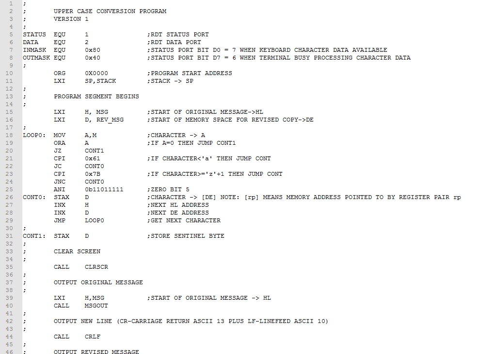
Example 1. Rework the Upper Case Conversion program from Experiment 7 to optimize for size. Our focus for optimizing will be to covert subtasks to subroutines. Subtasks that are repeated should be identified first. In this program, these are character output and message output tasks. We will make these into subroutines and replace the original assembly code with CALLs.
While replacing non-repeated tasks with subroutines may not save memory, doing so will often improve readability and manageability of the program. In this case we should look for subtasks that are general in function and not specifically related to the "main" task of the program. Clearing the screen and issuing a new line meet this criteria. These subtasks will also be replaced by CALLs to subroutines. Here is the size optimized program.
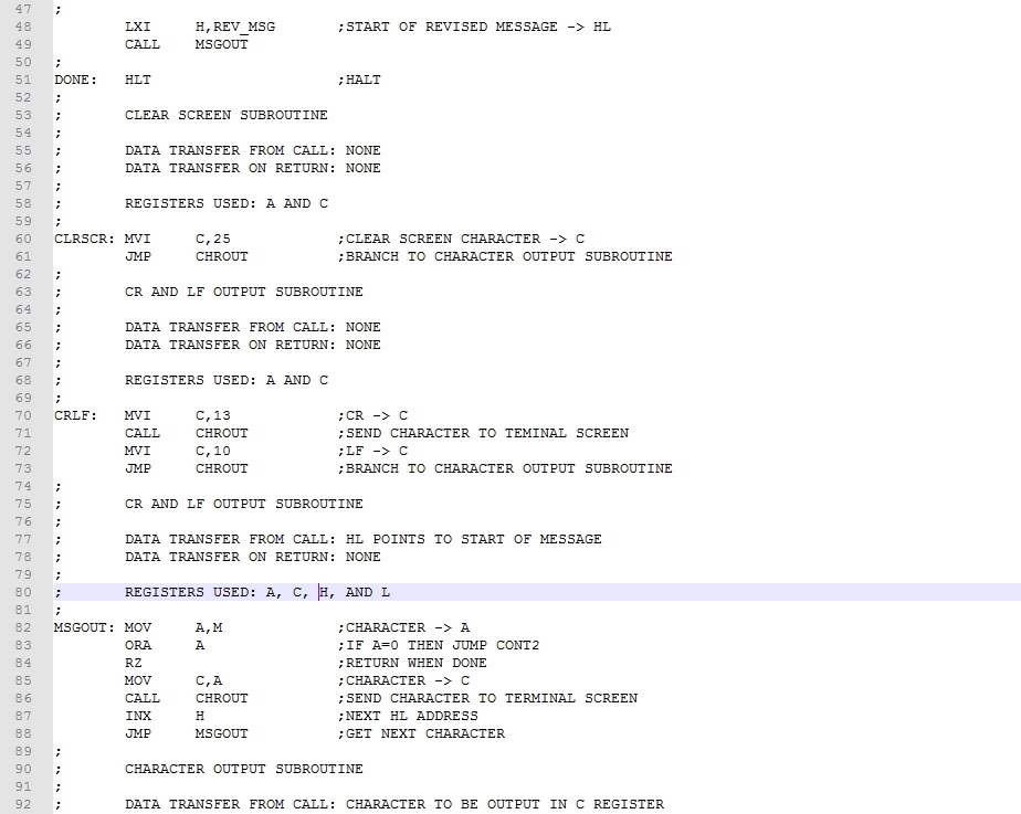
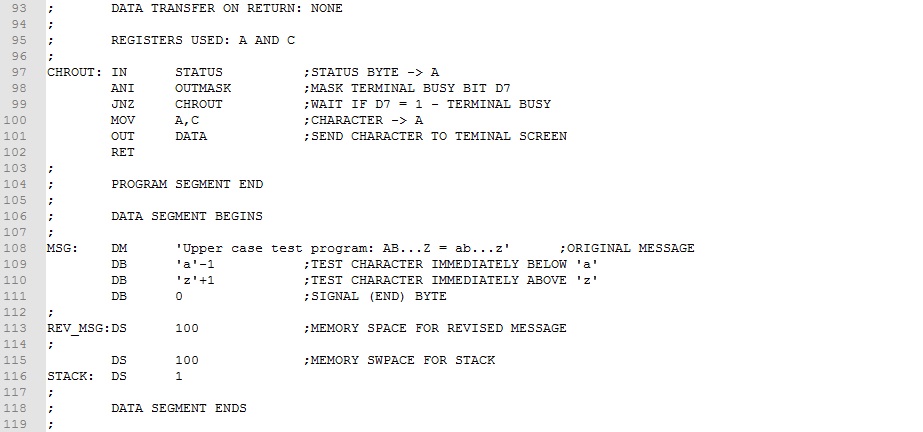
The four subtask code blocks has been converted to subroutines and collected together (lines 52-102) following the main program . Comments have been added designating how data is brought to the subroutine, how data is returned to the main program, and which registers are used. This is the type of information needed when inserting subroutine calls in the main program. Ignoring comment lines, we realize an assembly code saving of 16 bytes and machine code saving of 24 bytes about a 15% saving. Download this version of the program here. Assemble and test it.
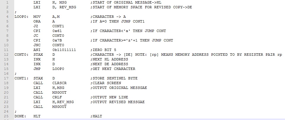
Referring to the main program (lines 11-52), if we streamline the comments, it takes on the more compact and readable form shown below. The subtask assembly code no longer clutters the main program making it easier to focus on the main task, upper case conversion. Provided the subroutines are debugged and working correctly, they can be extracted and used in other programs.
Example 2. Replace the in-memory message in the Upper Case Conversion Program with a keyboard entered message. Instead of using a halt command, make provision for more than one message to be entered. To address keyboard message entry, we will replace the read message from memory assembly code with code that takes characters from the keyboard and places them in a memory buffer. When a carriage return (Enter Key) is detected, the buffer input will be terminated and upper case conversion will proceed as before. Finally, instead of halting after the first message, execution will continue at the buffer input code to get another message.
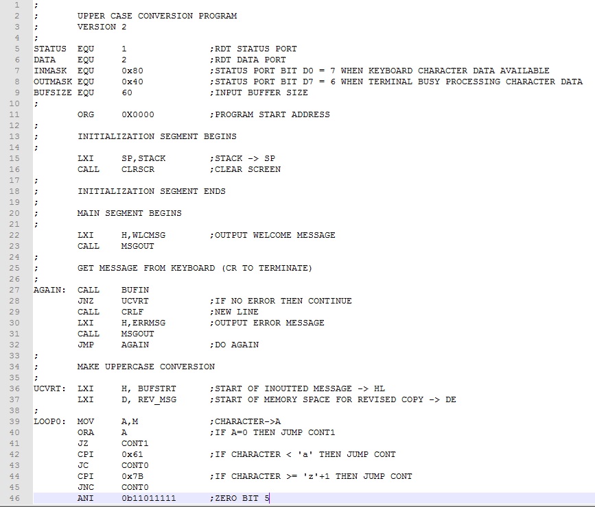
The program is similar to Example 1 with the following additions:
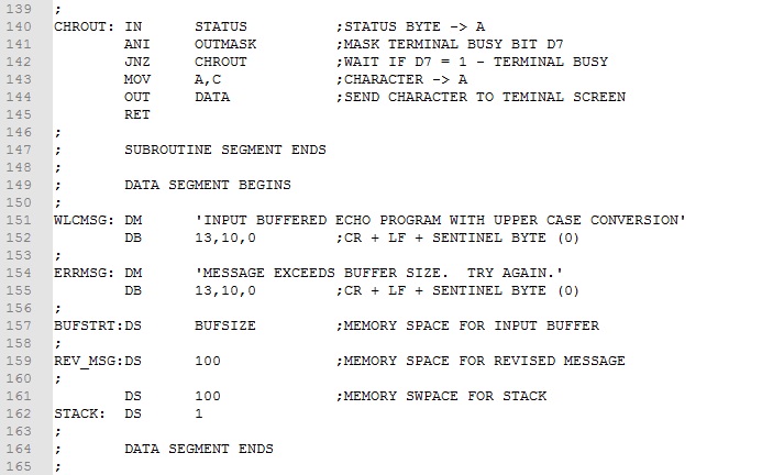
A welcome message is output when the program is first executed (lines 22-23).
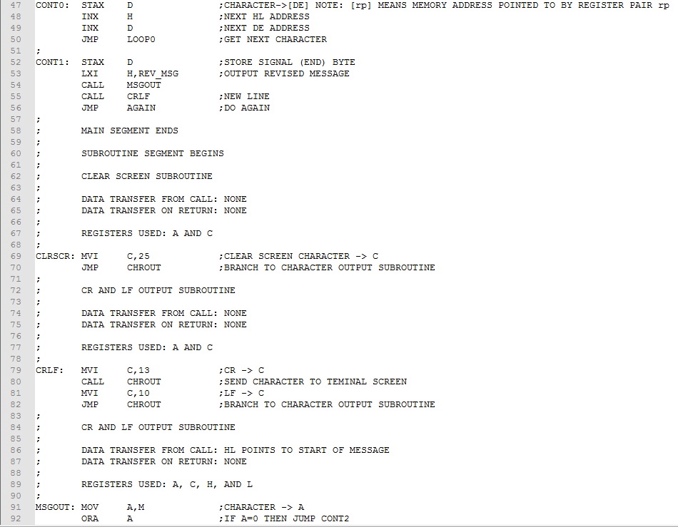
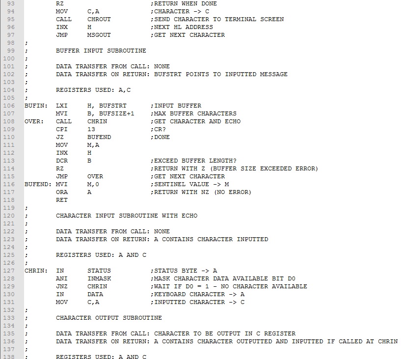
A buffer input subroutine (BUFIN) has been added that calls the keyboard input subroutine (CHRIN) and places the inputted characters in a memory buffer starting at BUFSTRT (lines 106-118). The buffer size (BUFSIZE) is taken into account and, if exceeded, the zero status bit is set signaling an error to the calling code.
The HLT has been replaced by a new line call and jump back to accept a new message (lines 55-56).
The segmentation of the program has been modified to include a initialization segment executed only once at startup; a main segment executed repeatedly; a subroutine segment with subroutines execute as required in the main segment; and a data segment where all program data resides.
This last item describes an overall structural form that is suitable for modular programing in general. By approaching the software design this way, the main segment can focus on the high level, non repetitive tasks to be performed. The other segments take on a supportive role. The readability and manageability of the program is greatly improved.
The initialization, main, and subroutine segments correspond to the setup method, loop method, and functions in Arduino programing. The next series of experiments will take up assembly coding with the Spark Fun Arduino Red Board. Stay tuned!
Download this version of the program here. Assemble and test it.
Continue to next Experiment - Click Here