Experiment 12 - Customizing AVR Tiny BASIC
In this experiment, we explore a version Tiny BASIC (TB) written for the
ATmega328 and learn how to customize it by adding statements and functions. Follow the procedure in Experiment 8 (see here)
for setting up an ATMEL Studio 7 project called "Experiment_12". Use the
"main.asm" found file here.
Note: The ZOC terminal is used in some of the example circuits.
Introduction to the AVR Version of Tiny BASIC
Tiny BASIC is great beginner's language with only nine
simple, English-like statements. In
addition, it is fully interactive giving novices immediate feedback and friendly
error messages when something is wrong.
Such a programming environment encourages beginners to experiment and try
new things. Despite its simplicity,
Tiny BASIC provides sufficient programming capabilities to create interesting
and useful programs.
Using the open source assembly language code (main.asm) referenced above,
we can customize the AVR version of Tiny BASIC.
In Examples 2 and 3 below, we explain in detail how to add a
pulse-width-modulation statement and analog-to-digital conversion
function. PWM(n) sends a pulse width modulated waveform of duty cycle
n% to pin 9 on the Redboard. ADC(n) reads the raw value
from A/D channel n (0 to 5) of the Redboard (A0 to A5). An added feature of the AVR version of Tiny BASIC is the
ability to encode a TB program in assembly then load and run it from power up or reset.
An introduction to AVR Tiny BASIC can be found
here.
Try it!
Example 1 - Run a test TB program.
Near the beginning of main.asm for Experiment_12
is the equate PLPrgm (Pre-Load Program). We'll use this later to load and run a
TB program on power up or system reset. For now, make sure that PLPrgm = 0
so that TB will operate in
the normal way and wait for user input to start. Build
the solution and program the ATmega328 flash memory. The
sign-on message and prompt ">" should appear on the ZOC terminal indicating TB
is ready to take commands or enter new program lines.
To test TB, enter the short program below and run it.
A list of die values from 1 to 6 should display.
10 REM Tiny BASIC program - Prints random die roll
20 PRINT "Enter number of die rolls to print";:INPUT N
30 LET C = 1
40 LET A=(RND(1)/1000+1):IF A>6 THEN 40
50 PRINT "Die Roll ";C;"=";A
60 LET C = C + 1:IF C <= N THEN 40
70 END
One valuable feature of the VOC terminal is that scrolled text can be copied
, pasted, and made into a text file using a text editor like Notepad++.
Simply LIST the program, select it, and paste it into a blank text file in
Notepad++. Save it as a text file (txt extension).
To reload it from the text file:
-
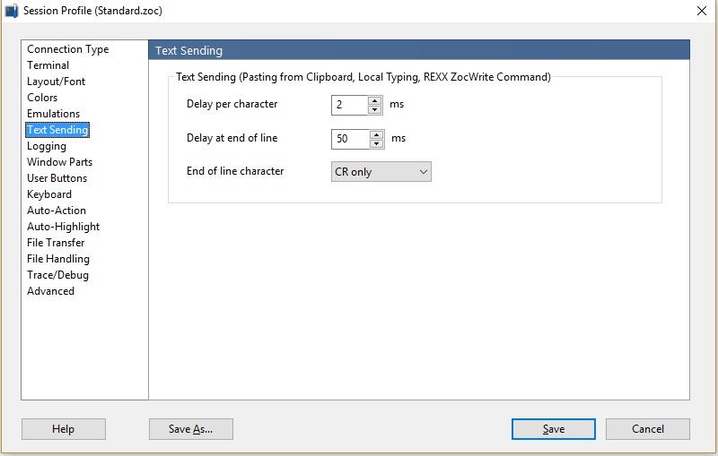
On the VOC terminal, click Options->Session
Profile. Click on "Text Sending". Make the changes shown
below and click "Save". This configuration change is necessary to allow time for processing
as lines of text are sent.
-
Enter the "new" command to clear out
any existing TB program.
-
On the VOC terminal, click Transfer->Textfile.
Navigate to where "Roll Die" was saved and select. Click "Open" and
the VOC Terminal will transmit the text file
line-by-line.
-
Enter the "list" command and check that the program has
loaded correctly. If so, enter "run" to execute the program.
To try out a longer TB program, load and run "HURKLE"
for AVR TB
here.
Note: The file type for a BASIC program would
normally be
"BAS"; however, "TXT" works better for the ZOC terminal. "TXT" files
are default and display immediately when "Open" is selected.
Customizing AVR Tiny BASIC
It might seem odd that after spending so much time with
assembly language, we would experiment with a high level language like AVR Tiny
BASIC. The thought behind this is that, with a little creativity, we might
create a version of Tiny BASIC customized for a particular class
of applications like robotics or data acquisition. In any case, let's work
through a couple of customizing examples.
If we stay with adding statements or functions, we'll see
that very few complications arise. Let's begin by reviewing some of the
basic concepts of TB.
-
TB is an interpreter. By that we mean that
the TB program is stored in SRAM as an ASCII text file.
In AVR Tiny BASIC, the line number is converted to a two-byte binary value, but
the remainder of the line is ASCII text. The interpretive execution code
uses an address pointer, the X register pair, to scan the program
and look for program elements like commands, statements, expressions, functions, etc.
When one is identified, the interpreter branches to an assembly language
routine that processes the identified program element.
-
Since we will be working at the statement or
function level only, much of the behind the scenes processing need not
be our concern. What we do need to know is explained below.
-
AVR TB was adapted from the original Intel
8080 version of TB. To make work simpler, ATmega328
registers were assigned Intel 8080 register names "A", "B", "C", etc. Generally, A is used like the
accumulator in the Intel 8080, the remaining registers (B, C, D,
E, H, L) can be used freely as working registers.
-
As noted above, the X register pair always points
to the ASCII text in the current TB program line. The "LD A, X"
instruction can be used to fetch the current TB program byte at any
time.
Since spaces are generally skipped, it is convenient and best to
use "RCALL skipSpace"
to scan from the current X address to the first non-space
TB program byte.
Upon return, the A register will contain the byte to be
processed.
-
After processing a byte and when ready
to scan forward to the next byte, use "RCALL nextByte" or "RCALL nextByteSS".
The former increments X to the next byte; the latter increments
the X register then scans to the next non-space byte. Upon
return in either case, the A register will contain the byte to
be processed.
Note: The X register must not be used for any other
purpose.
-
If the current byte is the beginning of a
numeric constant or expression, simply use "RCALL expression"
to fully process it. After return, the X register pair
will point to the byte following the end of the numeric constant or
expression and the two byte numeric result will be pushed on to
a special arithmetic stack. To retrieve the value from the
arithmetic stack,
use the macro "popRP H,L" to load it into HL. If two or more expressions are
processed, use multiple calls to "popRP" and remember that the returned values will be "last in"
then "first out" order!
-
When finished processing a statement,
point register pair X to the next non-space byte and execute
"RJMP done". Register pair X should point to a "CR" or
colon ":" character.
-
When finished processing a function,
place
the numeric result in register
pair HL and then execute a "RET" instruction.
-
To inform TB of a new statement or function:
-
For a new statement, keep the name as short
as possible (two or three letters is best) and carefully make
the following changes to the code below.
In the section below highlighted in
yellow, add all but
the last character in quotation marks ( " ) followed by
the last character in apostrophe marks ( ' ) plus " +
0x80," as shown. See the added bytes ""PW", 'M' +
0x80," in bold. We added
this to create the pulse-width-modulation statement of
Example 2 below. The number of bytes in the line was
even, so an added zero byte was unnecessary.
Note: The Command/Statement table is
searched for the current program statement when a TB
program line is
processed. Keeping names of frequently used
statements short and near the beginning of the table speeds up
processing. For this reason, "PWM" was inserted
ahead of "REM" and command names.
In the section highlighted in
green, insert a "RJMP" instruction in
the "iJmpTable" at the position corresponding to the name in the Command/Statement
list above. Note that the position of "PWM" jump
(in bold) is ninth as is the name "PWM" in the
Command/Statement list.
;
iTable:
;
; Note: Command/Statement reserved word table must match
iJmpTable!
;
.db "LE", 'T' + 0x80, 'I', 'F' + 0x80, "THE", 'N' + 0x80,
"PRIN", 'T' + 0x80, "GOT", 'O' + 0x80, "GOSU", 'B' + 0x80,
"RETUR", 'N' + 0x80, "INPU", 'T' + 0x80, "PW", 'M' + 0x80, "RE", 'M' +
0x80, "EN", 'D' + 0x80, "RU", 'N' + 0x80, "LIS", 'T' + 0x80,
"NE", 'W' + 0x80, 0xff
;
iJmpTable:
;
rjmp letInst
rjmp ifInst
rjmp gotoInst
rjmp printInst
rjmp gotoInst
rjmp gosubInst
rjmp returnInst
rjmp inputInst
rjmp pwmInst
rjmp remInst
rjmp endInst
rjmp runCommand
rjmp listCommand
rjmp newCommand
Place the custom statement code in the
section of "main.asm" designated "Start Custom Statements".
-
For a function, keep the name to
two or three characters and make the following changes to the
code below:
Follow the same
procedure as for a new statement adding "ADC" as shown.
See the code highlighted in
yellow.
Add a data byte (db) line
as shown in green changing
the label address to that of the new function. Be
sure that the position of the data byte line corresponds
to the position of the function name in the Function
list.
;
; Function Name Table
fTable:
;
; Note: Table must match fCallTable!
;
.db "RN", 'D' + 0x80, "AD", 'C' + 0x80,
0xff, 0
;
fCallTable:
;
.db low(getRandomNumber), high(getRandomNumber)
.db low(getADC), high(getADC)
;
Place the custom function subroutine in the section of
"main.asm" designated "Start Custom Functions".
Let's look at a couple of specific examples.
Try it!
Example 2 - Add pulse-width-modulation statement PWM(n) to
AVR Tiny BASIC where n is the percent duty cycle.
For PWM let's choose timer 1 compare register "A" as in
Experiment 11 Example Circuit 7.
We can borrow the PWM code from there and make it the core of our routine.
See the code highlighted in yellow below.
The single parameter is the percent duty cycle n as in
PWM(n). Upon arrival at our routine, register X will point to the byte
following "PWM" that should be an open parentheses "(". We choose to
use "LD A, X" rather than "rcall skipSpace" to enforce that there should be no spaces after "PWM". We
check for "(" and branch to a unpaired parentheses error if not present. If present we
point to the next byte skipping spaces. See the code highlighted in
green below.
We allow "n" to be an expression and "RCALL EXPRESSION".
After return, the value of "n" will be on the arithmetic stack and register pair X
will point to the byte immediately following the end of the expression. We used "RCALL skipSpace" allowing
spaces this time before the required ")". We could have been more restrictive and used "LD
A,X"; programmer's choice. See the code highlighted in
blue.
Next we pop the expression value off the arithmetic
stack into HL and check that it is between 0 and 100 inclusive. See the
code highlighted in orange.
HL is then passed to the "ocr1al" and "ocr1ah" I/O
registers to set the duty cycle. The PWM code highlighted in
yellow executes setting the pulse width on pin
9.
The last step is to move X beyond the closed parentheses
")" and branch to "done". See the code highlighted in
violet.
;
; Process PWM(n) Statement (n = percent duty cycle)
;
; Uses Timer 1 Compare Register "A" on Pin 9 of Redboard
;
pwmStmt:
;
ld
A, X
;Get first non-space byte
cpi
A, '('
;Should be equal sign?
breq pwmStmt0
;If so, continue
rjmp
unpairParenError ;Otherwise,
unpaired parentheses error
;
pwmStmt0:
;
rcall
nextByteSS
;Move to next byte then get first non-space byte
rcall
expression
;Evaluate expression
call
skipSpace
;Get first non-space byte
cpi A,
')'
;Should be equal sign?
breq pwmStmt1
;If so, continue
rjmp
unpairedParenError ;Otherwise, unpaired
parentheses error
;
pwmStmt1:
;
popRP H, L
;Get duty cycle
or
H,H
;HL should be 0 to 100, so H must be zero
breq pwmStmt2
;If so, continue
rjmp
overflowError
;Otherwise, overflow error
;
pwmStmt2:
;
mov A,L
cpi
A, 101
;L then should be 0 to 100 or less than 101
brcs pwmStmt3
;If so, continue
rjmp overflowError
;Otherwise, overflow error
;
pwmStmt3:
;
sbi
ddrb,1
;Set port b bit 1 (pin 9) output for timer 1 compare register "a"
ldi
A,0b00000011
;Prescaler timer 1 N=64 490 Hz
sts
TCCR1B,A
ldi
A,0b10000001
;Enable timer 1, clear on compare match, and PWM phase correct
;0bxxyy00zz xx = 10 enable to clear timer 1 compare register "a" on compare
match when up-counting
;
and set timer 1 compare register "a" on compare match when down-counting. (pin
9)
;
yy = 00 timer 1 compare register "b" not used
;
and set timer 1 compare register "b" on compare match when down-counting. (pin
10)
;
zz = 01 phase correct 8-bit mode
sts
TCCR1A,A
sts
ocr1al,L
;Preset timer 1 compare register "a" duty cycle = 0% (0 out of 255)
sts
ocr1ah,H
rcall nextByteSS
;Move to next byte then get first non-space byte - Should be a CR or ":"!
rjmp done
;Done
Connect a red LED from pin 9 through a 330 ohm resistor to ground. Build
the solution and program the ATmega328 flash memory. Use the ZOC
Terminal text transfer feature to load the text program below.
10 a=0
20 pwm(a)
30 a=a+1
40 b=0
50 b=b+1:if b<100 then 50
60 if a>100 then 10
70 goto 20
The LED should glow repeatedly dim and bright at a rate
determined by the delay value (100 to start) set in line 50.
Example 3 - Let's carry Example 2 one step further.
AVR TB can be configured to run a pre-stored TB program on
power up or reset.
First, let's look at how to include the program as part
of the assembly code. The program text is added at the point labeled "TB
Start-Up Program" as shown below. The PWM test program above has been
coded
into the data byte (.db) line shown. Text is included in quotation marks
as in "10 a=0" and at the end of each is a carriage return byte previously
defined with the label CR. After each line is a comma. At
the end of the program is the sentinel byte "0xff". The trailing zero is
needed to make an even
number of bytes in the line.
;
; TB Start-Up Program
;
TBProgram:
;
.db "10 a=0",CR, "20 pwm(a)", CR, "30 a=a+1", CR, "40 b=0", CR, "50 b=b+1:if
b<100 then 50", CR, "60 if a>100 then 10", CR, "70 goto 20", CR, 0xff, 0
;
The other change is the PLPrgm constant found near the
start of the assembly code. It should be set equal to 1 to indicate "load
and run" on start up.
Build the solution and program the ATmega328 flash
memory. The LED dimmer program should start immediately. It
will restart whenever the reset button is pressed.
Note: Change PLPrgm back to 0 before continuing with Example
3.
Example 3 - Add a analog-to-digital read function
ADC(n) to AVR TB where n is the A/D channel to be read (0 to 5).
For analog to digital conversion let's use the basic
code we developed in
Experiment 11 Example Circuit
3.
See the code highlighted in yellow below.
The code highlighted in green
below follows closely Example 2 above to get the parameter n on top of
the arithmetic stack.
The value of n is popped of
the arithmetic stack into HL using the macro "popRP H, L". The value is check
to be in the range 0 to 5. See the code highlighted in
blue.
The A/D code follows next with the value of n in
register ORed with the ADMUX configuration byte to select the A/D channel.
See the code highlighted in violet. The
A/D value (adch and adcl) is stored in H and L respectively and passed back
to the expression evaluation routine.
All that remains is to check for a closed parentheses
")", move to the next byte, and return (RET) with the A/D value in HL.
See the code highlighted in orange.
;intpH:
; Routine: getADC
;
; Purpose; For function DAC(n) gets A/D channel n value into HL
;
getADC:
;
rcall
skipSpace
;Open parentheses?
cpi
A, '('
breq
getADC1
;If so, cont...
rjmp
unpairedParenError
;If not, error
;
getADC1:
;
rcall
nextByte
;Point next byte
rcall
expression
;Get parameter
or
H,H
;Is H = 0?
brne
getADC2
;If so, continue
rjmp
overflowError
;If not, overflow error
;
getADC2:
;
cpi
L, 6
;Is L between 0 and 5
brcs
getADC3
;If so, continue
rjmp
overflowError
;Otherwise, overflow error
;
getADC3:
;
; Set Up Analog-to-Digital Converter
;
ldi
A,0b01000000 ;0bxxy0zzzz xx = 01 use
internal AVcc for reference (search "Table 28-3") ;
;
y = 0 right adjust result (search "Bit 5 – ADLAR")
;
zzzz = 0000 A/D channel 0 (search "Table 28-4")
or
A,L
;fix actual A/D channel
sts
admux,A
;ADC Multiplexer Selection Register (search "28.9.1")
;
ldi
A,0b11000111 ;0bxy000zzz x = 1
enable A/D (search "Bit 7 – ADEN")
;
y = 1 start conversion (search "Bit 6 – ADSC")
;
zzz = 111 prescale = 128 (search "Table 28-5")
sts
adcsra,A
;ADC Control and Status Register A (search "28.9.2")
;
getADC3:
;
lds A,adcsra
;check if a-d conversion complete?
sbrc
A,adsc
;adsc cleared?
rjmp
getADC3
;if not, wait
lds
L,adcl
;a-d result rawA/D in HL
lds
H,adch
;
rcall
skipSpace
;Close parentheses?
cpi
A, ')'
breq
getADC4
;If so, cont...
rjmp
unpairedParenError;If not, error...
;
getADC4:
;
rcall
nextByte
;Point next byte
ret
;Done...return
;
Build the solution and program the ATmega328 flash
memory. Connect the temperature sensor as in
Experiment 11 Example Circuit
3. Enter and run the AVR TB program below to test the code.
10 a=adc(0)
20 print "Temperature deg C = ";((a-102)*500+504)/1023;
30 print (a-102)*500/33*10/31
40 b=0
50 b=b+1:if b<10000 then 50
60 goto 10
The display should show the temperature to two and three
digits.
Note: In addition to the PWM statement and ADC function, the
customized version of AVR Tiny BASIC includes other statements and functions
that access ATmega328 peripherals. Refer to the AVR Tiny BASIC
Introduction document
here for
details.
This completes exploration of AVR Tiny BASIC.